Sign In
Upload
Manuals
Brands
IMS Manuals
DC Drives
MDrive 34 Plus Series
IMS MDrive 34 Plus Series Manuals
Manuals and User Guides for IMS MDrive 34 Plus Series. We have
1
IMS MDrive 34 Plus Series manual available for free PDF download: Hardware Reference Manual
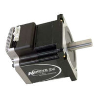
IMS MDrive 34 Plus Series Hardware Reference Manual (84 pages)
Motor+driver motion control
Brand:
IMS
| Category:
DC Drives
| Size: 3 MB
Table of Contents
Table of Contents
3
Getting Started - Mdriveplus Motion Control
7
Before You Begin
7
Tools and Equipment Required
7
Connecting the Power Supply
7
Connecting Communications
7
Install IMS Terminal Software
7
Establishing Communications
8
Figure GS.1: IMS Terminal Main Screen
8
Figure GS.2: IMS Terminal Prefrences Dialog
8
Apply Power to the Mdriveplus Motion Control
9
Testing the Mdriveplus Motion Control
9
Make the Mdriveplus Motion Control Move
9
Figure GS.3: Mdriveplus Motion Control Sign-On Message
9
Motion Control Example Using Program Mode
10
Programming Notes
10
Figure GS.4: Download the Program
10
Part 1: Hardware Specifications
11
Section 1.1: Mdrive34Plus Motion Control Product Introduction
11
Introduction to the Mdrive34Plus Motion Control System
13
Standard Feature Summary
13
Figure 1.1.1: Mdrive34Plus with Flying Leads
13
Figure 1.1.2: Mdrive34Plus
13
The Mdrive34Plus Motion Control Key Differences and Enhanced Features
14
Section 1.2: Mdrive34Plus Detailed Specifications
15
Standard Electrical Specifications
15
Thermal Specifications
15
Standard Motion Specifications
15
Software Specifications
16
Motor Specifications
16
Mechanical Specifications
17
Pin/Wire Assignments
18
P1 Connector - I/O and Power Connections
18
P2 Connector - RS-422/485 Communications
18
Options and Accessories
18
Figure 1.2.2: P1 - 12 In/304.8 CM Flying Leads
18
Figure 1.2.3: P2 - 10-Pin IDC, RS-422/485 Communications
18
Standard Electrical Specifications
19
Enhanced Electrical Specifications
19
Thermal Specifications
19
Standard Motion Specifications
19
Part 1: Hardware Specifications
19
Section 1.3: Mdrive34Plus2 Detailed Specifications
19
Enhanced Motion Specifications
20
Motor Specifications
21
Mechanical Specifications
21
Figure 1.3.1: Mechanical Specifications
21
Pin/Wire Assignments
22
P1 Connector - I/O and Power Connections
22
P2 Connector - RS-422/485 Communications
23
P3 Connector - Power
23
Options and Accessories
23
Figure 1.3.4: P2 10-Pin Wire Crimp Communications Connector
23
Figure 1.3.5: P3 2-Pin Locking Wire Crimp Power Connector
23
Part 2: Connecting and Interfacing
25
Section 2.1: Mounting and Connection Recommendations
25
Part 2: Connecting and Interfacing
27
Mounting Recommendations
27
DC Power Recommendations
27
Mdrive34Plus Motion Control
27
Layout and Interface Guidelines
27
Recommended Wiring
27
Locking Wire Crimp
27
Figure 2.1.1: Mdrive Motion Control Power Connections
27
Recommended Mating Connectors and Pins
28
Securing Power Leads and Logic Leads
28
Figure 2.1.2: Typical Mdrive Shown with Leads Secured
28
Part 2: Connections and Interface
29
Single Mode Communications Half Duplex (RS-485)
30
Interfacing Party Mode Communications
30
Data Cable Termination Resistors
30
Figure 2.2.2: Half Duplex 2 Wire Communications (RS-485)
30
Mdriveplus Motion Control Communication Format
31
Mdriveplus Motion Control (MDI) Response to Echo Mode
31
Figure 2.2.3: RS-485 Interface, Multiple Mdriveplus Motion Control System
31
Table 2.2.1: MDI Response to Echo Mode - Party and Check Sum Are Zero (0)
32
Using Check Sum
33
Table 2.2.4: MDI Response to Echo Mode - Party and Check Sum Are One (1)
33
Mdriveplus Motion Control Party Mode Sample Codes
34
Mdriveplus Motion Control Immediate Party Mode Sample Codes
35
Section 2.2: Interfacing Communications
29
Available Communications Cables/Converters
29
Interfacing Single Mode Communications
29
Single Mode Communications Full Duplex (RS-422)
29
Figure 2.2.1: Full Duplex Communications (RS-422)
29
Section 2.3: Interfacing and Using the Mdriveplus Motion Control I/O
36
The Mdriveplus Motion Control Digital I/O
36
Standard I/O Set
36
Enhanced I/O Set - Mdrive34Plus2
36
Uses of the Digital I/O
36
Figure 2.3.1: Uses for the Digital I/O
36
Mdriveplus Motion Control Digital Input Functions
37
Programmable Input Functions
37
Dedicated Input Functions
37
Active States Defined
37
Table 2.3.1: Programmable Input Functions
37
Table 2.3.2: Dedicated Input Functions
37
Mdriveplus Motion Control Digital Output Functions
38
Programmable Output Functions
38
Dedicated Output Functions
38
Table 2.3.3: Programmable Output Functions
38
Table 2.3.4: Dedicated Output Functions
38
Mdriveplus Motion Control I/O Ratings
39
Mdriveplus Motion Control I/O Connections
39
Figure 2.3.2: P1 - 12 In/304.8 CM Flying Leads
39
Table 2.3.5: Mdriveplus Motion Control I/O and Protection Ratings
39
Table 2.3.6: Mdrive34Plus P1 I/O
39
Table 2.3.7: P1 Pin Descriptions
39
I/O Usage Examples - Mdriveplus Standard I/O Set
40
Input Interface Example - Switch Input Example (Sinking Input)
40
Figure 2.3.5: Sinking Input Example Using a Push Button Switch
40
Input Interface Example - Switch Input Example (Sourcing Input)
41
Figure 2.3.6: Sourcing Input Example Using a Push Button Switch
41
Output Interface Example (Sinking Output)
42
Figure 2.3.7: Sinking Output Example
42
General Purpose I/O Usage Examples - Enhanced I/O Set
43
Input Interface Example - Switch Input Example (Sinking Input)
43
Figure 2.3.8: Switch Interface to Input, Sinking
43
Input Interface Example - Switch Input Example (Sourcing Input)
44
Figure 2.3.9 Sourcing Input Example Using a Push Button Switch
44
Output Interface Example (Sinking Output)
45
Figure 2.3.10: Sinking Output Example
45
Output Interface Example (Sourcing Output)
46
Figure 2.3.11: Sourcing Output Example
46
Dedicated Digital I/O - Enhanced I/O Set
47
Step/Direction/Clock I/O
47
Capture/Trip
47
Figure 2.3.12: Mdriveplus Motion Control Clock Functions
47
Interfacing the Analog Input
48
Sample Usage
48
Figure 2.3.13: Analog Input - Voltage Mode
48
Figure 2.3.14: Analog Input - Current Mode
49
Appendix F: Optional Cables and Cordsets
51
Appendices
51
Appendices
53
Appendix A: Mdriveplus Motion Control Motor Performance
53
Speed-Torque Curves/Motor Specifications
53
Figure A.1: Mdrive34Plus Motion Control Speed-Torque Curves
53
Appendix B: Recommended Power and Cable Configurations
54
Example a - Cabling under 50 Feet, DC Power
54
Example B - Cabling 50 Feet or Greater, AC Power to Full Wave Bridge
54
Example C - Cabling 50 Feet or Greater, AC Power to Power Supply
54
Figure B.1: DC Cabling - under 50 Feet
54
Figure B.2: DC Cabling - 50 Feet or Greater - AC to Full Wave Bridge Rectifier
54
Figure B.3: AC Cabling - 50 Feet or Greater - AC to Power Supply
54
Recommended IMS Power Supplies
55
Recommended Power Supply Cabling
55
Table B.1: Recommended Supply Cables
55
Appendix C: Planetary Gearboxes
56
Section Overview
56
Product Overview
56
Selecting a Planetary Gearbox
56
Calculating the Shock Load Output Torque (TAB
57
Figure C.1: Mdrive23 Torque-Speed Curve
58
Table C.1: Planetary Gearbox Operating Factor
59
System Inertia
60
Figure C.2: Lead Screw System Inertia Considerations
60
Figure C.3: Rack and Pinion System Inertia Considerations
61
Figure C.4: Conveyor System Inertia Considerations
61
Figure C.5: Rotary Table System Inertia Considerations
62
Figure C.6: Chain Drive System Inertia Considerations
63
Planetary Gearbox Inertia
64
Table B.2: Planetary Gearbox Inertia Moments
64
Figure C.7: Planetary Gearbox Specifications for Mdrive34Plus Motion Control
65
Table B.3: Planetary Gearbox Specifications
65
Table B.4: Planetary Gearbox Ratios and Part Numbers
65
Appendix D: I/O Application Guide
67
Standard I/O Set Interfacing and Application
67
Figure D.1: NPN Interface to an MDI Sinking Input
67
Figure D.2: PNP Interface to a Sourcing Input
68
Figure D.4: Mixed Output Example- Standard I/O Set
69
Mixed Input/Output Example
69
Sinking Output
69
NPN Sinking Input
70
PNP Sourcing Input
70
Enhanced I/O Set Interfacing and Application
70
Sourcing Output
71
Mixed Input/Output Example
72
Interfacing Inputs as a Group Example
72
Figure D.9: TTL Interface to an Input Group
72
Interfacing Outputs as a Group Example
73
Figure D.10: Outputs Interfaced to Led's as a Group
73
Table D.1: Output Bit Weight Examples - Outputs Set as a Group
73
Mdriveplus Motion Control Closed Loop Control
74
Appendix E: Mdrive Motion Control Closed Loop Options
74
Internal Encoder
74
Figure E.1: Connecting a Remote Encoder
75
Communications Converter Cables
76
USB to 10-Pin IDC (MD-CC400-000
76
Figure F.1: MD-CC400-000
76
Figure F.2: MD-CC400-000 Mechanical Specifications
76
Table F.1: MD-CC400-000 Electrical Specifications
76
Installation Procedure for the MX-Cc40X-000
77
Installing the Cable/Vcp Drivers
77
Figure F.3: Typical Communications Interface
77
Figure F.4: Hardware Update Wizard
77
Figure F.7: Windows Logo Compatibility Testing
78
Figure F.8: Hardware Update Wizard Finish Installation
78
Figure F.5: Hardware Update Wizard Screen 2
78
Determining the Virtual COM Port (VCP
79
Prototype Development Cables
79
Figure F.10: Windows Device Manager
79
Figure F.9: Hardware Properties
79
Figure F.12: PD02-3400-FL3
80
Prototype Development Cable - PD02-3400-FL3
80
Prototype Development Cable PD14-2334-FL3
80
Figure F.13: PD10-1434-FL3
81
Prototype Development Cable - PD10-1434-FL3
81
Advertisement
Advertisement
Related Products
IMS HEAVYMIG 350-4
IMS HEAVYMIG 350 GR
IMS PULSEMIG 300-T2
IMS IB462H
IMS MDRIVE 23
IMS MFORCE MICRO DRIVE Plus MICROSTEPPING
IMS Categories
Welding System
DC Drives
Industrial Equipment
Computer Hardware
Home Safety Product
More IMS Manuals
Login
Sign In
OR
Sign in with Facebook
Sign in with Google
Upload manual
Upload from disk
Upload from URL