Sign In
Upload
Manuals
Brands
IMS Manuals
DC Drives
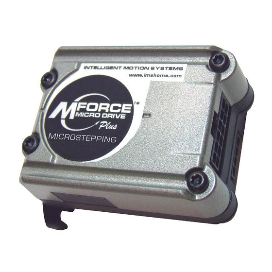
MFORCE MICRO DRIVE Plus MICROSTEPPING
IMS MFORCE MICRO DRIVE Plus MICROSTEPPING Manuals
Manuals and User Guides for IMS MFORCE MICRO DRIVE Plus MICROSTEPPING. We have
1
IMS MFORCE MICRO DRIVE Plus MICROSTEPPING manual available for free PDF download: Operating Instructions Manual
IMS MFORCE MICRO DRIVE Plus MICROSTEPPING Operating Instructions Manual (64 pages)
Brand:
IMS
| Category:
DC Drives
| Size: 4 MB
Table of Contents
Table of Contents
3
Getting Started: Microstepping Mforce Microdrive
7
Before You Begin
7
Tools and Equipment Required
7
Connecting the Power Supply
7
Connect Opto Reference and Logic Inputs
7
Connecting the Motor
7
Figure GS.1: Minimum Logic and Power Connections
7
Part 1: Hardware Reference
9
Section 1.1: Introduction to the Microstepping Mforce Microdrive
9
Configuring
11
Features and Benefits
12
Section 1.2: Microstepping Mforce Microdrive Detailed Specifications
13
General Specifications
13
Part 1: Hardware Reference
14
Part 1: Hardware Reference
14
Setup Parameters
14
Mechanical Specifications
14
Figure 1.2.1: Mforce Microdrive Mechanical Specifications
14
Table 1.2.1: Setup Parameters
14
Pin Assignment and Description
15
P1 Connector - Power and I/O
15
Figure 1.2.2: P1 Connector - I/O and Power
15
Table 1.2.2: P1 - Pin Assignment, Power and I/O
15
P2 Connector - SPI Communications
16
Figure 1.2.3: P2 Connector - SPI Communications
16
Table 1.2.3: P2 Connector - SPI Communications
16
P1 12-Pin Locking Wire Crimp Connector Option
17
Figure 1.2.4: P1 - 12-Pin Locking Wire Crimp
17
Table 1.2.4: P1 Connector - Power, I/O and SPI Communications
17
P3 Connector - Motor Phase Connector
18
Figure 1.2.5: P3 - 4-Pin Locking Wire Crimp Motor Connector
18
Table 1.2.5: P3 - Pin Assignment, Motor Phase Connections
18
Part 2: Connecting and Interfacing
19
Section 2.1: Mounting and Connection Recommendations
19
Part 2: Connecting and Interfacing
21
Mounting Recommendations
21
Thermal Considerations
21
Layout and Interface Guidelines
21
Recommended Wiring
21
Securing Power Leads and Logic Leads
21
Figure 2.1.1: Mforce Microdrive Mounting Recommendations
21
DC Power Recommendations
22
Microstepping Mforce Microdrive
22
Recommended DC Power Supply Connections
22
Figure 2.1.2: Microstepping Mforce Microdrive Power Connections
22
Section 2.2: Logic Interface and Connection
23
Optically Isolated Logic Inputs
23
Isolated Logic Input Pins and Connections
23
Isolated Logic Input Characteristics
23
Enable Input
23
Figure 2.2.1: Isolated Logic Pins and Connections
23
Clock Inputs
24
Figure 2.2.2: Input Clock Functions
24
Figure 2.2.3: Clock Input Timing Characteristics
25
Table 2.2.1: Input Clocks Timing Table
25
Part 1: Interfacing and Configuring
25
Optocoupler Reference
26
Figure 2.2.4: Optocoupler Input Circuit Diagram
26
Table 2.2.2: Optocoupler Reference Connection
26
Input Connection Examples
27
Figure 2.2.5: Open Collector Interface Example
27
Figure 2.2.6: Switch Interface Example
28
Switch Interface Example
28
Minimum Required Connections
29
Figure 2.2.7: Minimum Required Connections
29
Section 2.3: Connecting SPI Communications
30
Connecting the SPI Interface
30
SPI Signal Overview
30
Figure 2.3.1: MD-CC300-000 Parameter Setup Cable
30
SPI Pins and Connections
31
Figure 2.3.2: SPI Pins and Connections, 10-Pin IDC
31
Figure 2.3.3: SPI Pins and Connections, 12-Pin Wire Crimp
31
SPI Master with Multiple Microstepping Mforce Microdrive
32
Figure 2.3.4: SPI Master with a Single Microstepping Mforce Microdrive
32
Figure 2.3.5: SPI Master with Multiple Microstepping Mforce Microdrives
32
Section 2.4: Using the IMS SPI Motor Interface
33
Installation
33
Configuration Parameters and Ranges
33
Color Coded Parameter Values
33
Table 2.4.1: Setup Parameters and Ranges
33
IMS SPI Motor Interface Menu Options
34
Figure 2.4.1: SPI Motor Interface Color Coding
34
Figure 2.4.2: SPI Motor Interface File Menu
34
Figure 2.4.3: SPI Motor Interface View Menu
34
Figure 2.4.4: SPI Motor Interface Recall Menu
35
Figure 2.4.5: SPI Motor Interface Upgrade Menu
35
Figure 2.4.6: SPI Motor Interface Help Menu and about Screen
35
Screen 1: the Motion Settings Configuration Screen
36
MSEL (Microstep Resolution Selection)
36
Figure 2.4.7: SPI Motor Interface Motion Settings Screen
36
Table 2.4.2: Microstep Resolution Settings
36
HCDT (Hold Current Delay Time)
37
MRC (Motor Run Current)
37
MHC (Motor Hold Current)
37
DIR (Motor Direction)
37
User ID
37
IMS SPI Motor Interface Button Functions
37
Screen 2: I/O Settings Configuration Screen
38
Input Clock Type
38
Input Clock Filter
38
Enable Active High/Low
38
Figure 2.4.8: SPI Motor Interface I/O Settings Screen
38
IMS Part Number/Serial Number Screen
39
Fault Indication
39
Figure 2.4.9: SPI Motor Interface Part and Serial Number Screen
39
Upgrading the Firmware in the Microstepping Mforce Microdrive
40
The IMS SPI Upgrader Screen
40
Upgrade Instructions
40
Figure 2.4.10: SPI Motor Interface Upgrade Utility
40
Initialization Screen
41
Port Menu
41
Figure 2.4.11: SPI Motor Interface Initialization
41
Figure 2.4.12: SPI Motor Interface Port Menu
41
Section 2.5: Using User-Defined SPI
42
SPI Timing Notes
42
Check Sum Calculation for SPI
42
Figure 2.5.1: SPI Timing
42
SPI Commands and Parameters
43
Table 2.5.1: SPI Commands and Parameters
43
Figure 2.5.2: Read/Write Byte Order for Parameter Settings (Default Parameters Shown)
44
SPI Communications Sequence
44
Appendices
45
Appendices
47
Appendix A: Recommended Power and Cable Configurations
47
Example a - Cabling under 50 Feet, DC Power
47
Example B - Cabling 50 Feet or Greater, AC Power to Full Wave Bridge
47
Example C - Cabling 50 Feet or Greater, AC Power to Power Supply
47
Figure A.1: DC Cabling - under 50 Feet
47
Figure A.2: DC Cabling - 50 Feet or Greater - AC to Full Wave Bridge Rectifier
47
Figure A.3: AC Cabling - 50 Feet or Greater - AC to Power Supply
47
Appendices
48
Recommended IMS Power Supplies
48
Recommended Power Supply Cabling
48
Table A.1: Recommended Supply Cables
48
Appendix B: Encoder Options
49
General Specifications
49
Appendix B: Encoder Options
50
Encoder Signals
50
Differential Encoder
50
Characteristics
50
Encoder Cables
51
Recommended Encoder Mating Connectors
51
Appendix C: Optional Prototype Development Cables
52
MD-CC300-000: USB to SPI Parameter Setup Cable
52
Adapter Cables
52
Figure C.1: MD-CC300-000
52
Figure C.2: MD-CC300-000 Mechanical Specifications
52
Installation Procedure for the MD-CC300-000
53
Installing the Cable/Vcp Drivers
53
Figure C.3: Typical Setup, Adapter and Prototype Development Cable
53
Figure C.4: Hardware Update Wizard
53
Figure C.7: Windows Logo Compatibility Testing
54
Determining the Virtual COM Port (VCP
55
Figure C.8: Hardware Update Wizard Finish Installation
55
Figure C.9: Hardware Properties
55
Figure C.10: Windows Device Manager
55
PD12-1434-FL3 - Power, I/O and SPI
56
Figure C.11 PD12-1434-FL3
56
Table C.1: PD12-1434-FL3 Wire Color Codes
56
Appendix D: IMS Enhanced Torque Stepping Motors
57
Size 14 Enhanced Torque Stepping Motor
57
General Specifications
57
Wiring and Connection
57
Mechanical Specifications
57
Figure D.1: Size 14 Wiring and Connection
57
Figure D.2: Size 14 Mechanical Specifications
57
Table D.1: Size 14 General Specifications
57
Size 17 Enhanced Torque Stepping Motor
58
General Specifications
58
Wiring and Connection
58
Speed Torque Curves
58
Figure D.3: Size 17 Wiring and Connection
58
Figure D.4: Size 17 Speed Torque Curves
58
Table D.2: Size 17 General Specifications
58
Mechanical Specifications
59
Figure D.5: Size 17 Mechanical Specifications
59
Size 23 Enhanced Torque Stepping Motor
60
General Specifications
60
Wiring and Connection
60
Speed Torque Curves
60
Figure D.6: Size 23 Wiring and Connection
60
Figure D.7: Size 17 Speed Torque Curves
60
Table D.3: Size 23 General Specifications
60
Advertisement
Advertisement
Related Products
IMS MDRIVE 23
IMS Mforce micro drive
IMS MDrive34Plus
IMS Digital Marine Recording System
IMS MPC1005
IMS MM1000
IMS MS120S01
ims Medio
IMS MM500
IMS Mini
IMS Categories
Welding System
DC Drives
Industrial Equipment
Computer Hardware
Home Safety Product
More IMS Manuals
Login
Sign In
OR
Sign in with Facebook
Sign in with Google
Upload manual
Upload from disk
Upload from URL