Sign In
Upload
Manuals
Brands
IEI Technology Manuals
Single board computers
WAFER-EHL2
IEI Technology WAFER-EHL2 Manuals
Manuals and User Guides for IEI Technology WAFER-EHL2. We have
1
IEI Technology WAFER-EHL2 manual available for free PDF download: User Manual
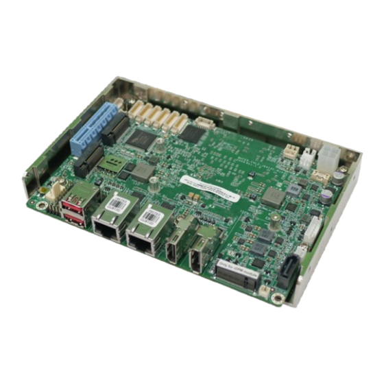
IEI Technology WAFER-EHL2 User Manual (147 pages)
3.5" SBC supports Intel Celeron J6412 on-board SoC with 8GB LPDDR4x memory on board default, dual display with HDMI and iDPM slot, dual 2.5 GbE, USB 3.2 Gen 2, M.2, SATA 6Gb/s, 6 COM, iAUDIO
Brand:
IEI Technology
| Category:
Single board computers
| Size: 20 MB
Table of Contents
Revision
2
Table of Contents
5
Introduction
13
Ntroduction
14
Figure 1-1: WAFER-EHL2
14
Features
15
Connectors
15
Dimensions
16
Figure 1-3: Dimensions (MM)
16
Data Flow
17
Figure 1-4: Data Flow Diagram
17
Technical Specifications
18
Table 1-1: Technical Specifications
19
Unpacking
20
Anti-Static Precautions
21
Unpacking Precautions
21
Packing List
22
Table 2-1: Packing List
22
Table 2-2: Optional Items
23
Connectors
24
Peripheral Interface Connectors
25
WAFER-EHL2 Layout
25
Figure 3-1: Connector and Jumper Locations
25
Figure 1-2: Connectors
26
External Interface Panel Connectors
27
Internal Peripheral Connectors
27
Clear CMOS Button
27
Table 3-1: Peripheral Interface Connectors
27
Table 3-2: Rear Panel Connectors
27
Figure 3-2: Clear CMOS Location
28
Table 3-3: Clear CMOS Pinouts
28
AT/ATX Power Mode Setting
29
Figure 3-3: AT/ATX Power Mode Switch Locations
29
Table 3-4: AT/ATX Power Mode Switch Pinouts
29
DNX Mode Setting Jumper
30
Figure 3-4: DNX Mode Setting Jumper Location
30
Table 3-5: DNX Mode Setting Jumper Pinouts
30
Flash Descriptor Override Setting Jumper
31
Figure 3-5: Flash Descriptor Override Setting Jumper Locations
31
Table 3-6: Flash Descriptor Override Setting Jumper Pinouts
31
Internal Audio Connector
32
Figure 3-6: Audio Connector Location
32
ATX 12V Power Connector
33
Figure 3-7: ATX 12V Power Connector Location
33
Table 3-7:Audio Connector Pinouts
33
Table 3-8: ATX 12V Power Connector Pinouts
33
RTC Battery Connector
34
Buzzer Connector
35
Figure 3-8: Battery Connector Location
35
Table 3-9: Battery Connector Pinouts
35
Chassis Status Connector
36
Figure 3-9: Buzzer Connector Location
36
Table 3-10: Buzzer Connector Pinouts
36
Digital Input/Output Connector
37
Figure 3-10 Chassis Open Connector Location
37
Table 3-11 Chassis Status Connector Pinouts
37
Fan Connector
38
Figure 3-11: Digital I/O Connector Location
38
Table 3-12: Digital I/O Connector Pinouts
38
Figure 3-12: Fan Connector Location
39
Table 3-13: Fan Connector Pinouts
39
Power LED & HDD LED Connector
40
Figure 3-13: Power LED & HDD LED Connector Location
40
Table 3-14: Power LED & HDD LED Connector Pinouts
40
Power Button Connector
41
Figure 3-14: Power Button Connector Location
41
Table 3-15: Power Button Connector Pinouts
41
Reset Button Connector
42
Figure 3-15: Reset Button Connector Location
42
Table 3-16: Reset Button Connector Pinout
42
Serial Port Connector
43
Figure 3-16: RS-232 Serial Port Connector Location
43
Table 3-17: RS-232 Serial Port Connector Pinouts
43
RS-232/422/485 Serial Port Connectors
44
Figure 3-17 RS-232/422/485 Serial Port Connector Location
44
Table 3-18 RS-232/422/485 Serial Port Connector Pinouts
44
SATA 6Gb/S Drive Connector
45
Figure 3-18: SATA 6Gb/S Drive Connectors Location
45
Table 3-19: SATA 6Gb/S Drive Connectors Pinouts
45
SATA Power Connector
46
Figure 3-19: SATA Power Connector Location
46
Table 3-20: SATA Power Connector Pinouts
46
I 2 C Connector
47
Figure 3-20: I² C Connector Location
47
Table 3-21: I²C Connector Pinouts
47
Smbus Connector
48
Figure 3-21: Smbus Connector Location
48
Table 3-22: Smbus Connector Pinouts
48
Flash SPI ROM Connector
49
Figure 3-22: Flash SPI ROM Connector Location
49
Table 3-23: Flash SPI ROM Connector Pinouts
49
EC Debug Connector
50
Figure 3-23: EC Debug Connector Location
50
Table 3-24:EC Debug Connector Pinouts
50
Internal USB 2.0 Connectors
51
Figure 3-24: Internal USB 2.0 Connectors Locations
51
Table 3-25: Internal USB 2.0 Connectors Pinouts
51
A-Key Slot
52
Figure 3-25: M.2 A-Key Slot Location
52
Table 3-26: M.2 A-Key Slot Pinouts
53
B-Key Slot
54
Figure 3-26: M.2 B-Key Slot Location
54
Table 3-27: M. 2 B-Key Slot Pinouts
55
SIM Card Slot
56
Figure 3-27: SIM Card Slot Location
56
Table 3-28: SIM Card Slot Pinouts
56
External Peripheral Interface Connector Panel
57
External 2.5Gbe RJ-45 Connectors
57
Figure 3-28: External Peripheral Interface Connector
57
Table 3-29: External 2.5Gbe RJ-45 Connectors Pinouts
57
External DP Connector
58
Figure 3-29: LAN LED Location
58
Table 3-30: LAN LED Pinouts
58
Table 3-31: External Displayport Connector Location
58
External HDMI Connectors
59
Figure 3-30: External DP Connector Pinouts
59
Figure 3-31: External HDMI Connector Location
59
Table 3-32: External HDMI Connector Pinouts
59
External USB 3.2 Gen 2 Connectors
60
Figure 3-32: External USB 3.2 Gen 2 Connectors Location
60
Table 3-33: External USB 3.2 Gen 2 Connectors Pinouts
60
Installation
61
Anti-Static Precautions
62
Installation Considerations
63
Module Installation
64
Figure 4-1: Inserting the M.2 Module into the Slot at an Angle
64
Chassis Installation
65
Heat Spreader
65
Figure 4-2: Securing the M.2 Module
65
Figure 4-3 Heat Sink Retention Screws
66
Figure 4-4 Passive Cooling
66
Figure 4-5 Active Cooling
66
Motherboard Installation
67
Figure 4-6: DRPC-W-EHL22-R10 Figure 4-7: DRPC-W-EHL22-R10 with Extra Fan
67
Riser Card Installation
68
Figure 4-8: Motherboard Installation Example
68
Figure 4-9:Outwards Riser Card Installation Example Figure 4-10: NWR-L2S-R10
68
Figure 4-11: Inwards Riser Card Installation Example Figure 4-12: NWR-R2S-R10
69
Figure 4-13:L-Shaped Bracket Installation Example
69
Internal Peripheral Device Connections
70
AT Power Connection
70
Figure 4-14: Power Cable to Motherboard Connection
70
Channel Audio Kit Installation
71
Figure 4-15: Connect Power Cable to Power Supply
71
SATA Drive Connection
72
Figure 4-16: 7.1 Channel Audio Kit
72
Figure 4-17: SATA Drive Cable Connection
73
Software Drivers
74
Available Drivers
74
Driver Download
74
Figure 4-18: IEI Resource Download Center
74
Bios
76
Introduction
77
Starting Setup
77
Figure 5-1: BIOS Starting Menu
77
Using Setup
78
Keyboard Navigation
78
Table 5-1: BIOS Navigation Keys
78
Touch Navigation
79
Table 5-2: BIOS On-Screen Navigation Keys
79
Getting Help
80
Unable to Reboot after Configuration Changes
80
BIOS Menu Bar
80
Main
81
Advanced
85
CPU Configuration
86
Trusted Computing
91
F81804 Super IO Configuration
92
Serial Port 1 Configuration
93
Serial Port 2 Configuration
94
Serial Port 3 Configuration
95
Serial Port 4 Configuration
97
Serial Port 5 Configuration
98
Serial Port 6 Configuration Menu
100
ENE KB9068 Monitor
102
Smart Fan Mode Configuration
103
Serial Port Console Redirection
104
Console Redirection Settings
105
Nvme Configuration
108
Chipset
109
System Agent (SA) Configuration
110
Memory Configuration
111
Graphics Configuration
112
PCH-IO Configuration
115
Figure 5-2: BIOS Options and Configured USB Ports
117
PCI Express Configuration
118
Pcie Root Port Setting
118
M2_A_KEY Slot
120
M2_B_KEY Slot
122
SATA Configuration
124
HD Audio Configuration
126
Security
127
Boot
128
Boot Configuration
128
Boot Option Priorities
129
Save & Exit
130
A Regulatory Compliance
132
B Product Disposal
134
CBIOS Options
136
D Watchdog Timer
140
E Error Beep Code
143
Pei Beep Codes
144
Dxe Beep Codes
144
F Hazardous Materials Disclosure
145
Rohs II Directive (2015/863/EU)
146
China Rohs
147
Advertisement
Advertisement
Related Products
IEI Technology WAFER-EHL-J6412
IEI Technology WAFER-EHL2-J6412
IEI Technology WAFER-EHL2-J6412C-R10
IEI Technology WAFER-MARK
IEI Technology WAFER-TGL
IEI Technology WAFER-TGL-U-i3-R11
IEI Technology WAFER-RK3588-A/CE
IEI Technology WAFER-IMX8MP-U/BD
IEI Technology WAFER-IMX8MP-A/BD
IEI Technology WAFER-IMX8MP
IEI Technology Categories
Motherboard
Touch Panel
Computer Hardware
Single board computers
Desktop
More IEI Technology Manuals
Login
Sign In
OR
Sign in with Facebook
Sign in with Google
Upload manual
Upload from disk
Upload from URL