Sign In
Upload
Manuals
Brands
IEI Technology Manuals
Motherboard
WAFER-LX2-800
IEI Technology WAFER-LX2-800 Manuals
Manuals and User Guides for IEI Technology WAFER-LX2-800. We have
2
IEI Technology WAFER-LX2-800 manuals available for free PDF download: User Manual, Quick Installation Manual
IEI Technology WAFER-LX2-800 User Manual (186 pages)
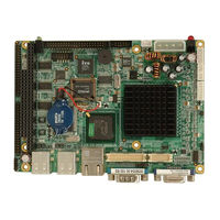
AMD Geode? LX 800 3.5" Single Board Computer Eight serial ports, Audio, PC/104 Expansion and supports CompactFlash and IDE
Brand:
IEI Technology
| Category:
Motherboard
| Size: 8.67 MB
Table of Contents
User Manual
1
Packing List
6
Table of Contents
7
1 Introduction
19
Figure 1-1: WAFER-LX2
20
Figure 1-2: WAFER-LX2 Overview
22
Wafer-Lx2 Overview
22
Figure 1-3: WAFER-LX2 Solder Side Overview
23
Technical Specifications
24
Table 1-1: Technical Specifications
25
WAFER-LX2 Connectors
23
Wafer-Lx2 Overview
20
WAFER-LX2 Applications
20
WAFER-LX2 Benefits
20
WAFER-LX2 Features
21
2 Detailed Specifications
26
Dimensions
27
Board Dimensions
27
External Interface Panel Dimensions
27
Figure 2-1: WAFER-LX2 Dimensions (MM)
27
Figure 2-2: External Interface Panel Dimensions (MM)
28
Figure 2-3: Data Flow Block Diagram
29
AMD Geode™ LX 800 500Mhz Display Support
30
AMD Geode™ LX 800 500Mhz Graphics Processor
30
AMD Geode™ LX 800 Memory Support
30
Table 2-1: Geode LX Graphics Features
31
AMD Geode™ LX 800 500Mhz Power Management
32
Geodelink™ Interface Unit
32
System Chipset
32
AMD Geode™ CS5536 ATA-6 Controller
33
AMD Geode™ CS5536 Audio Codec 97 (AC'97) Controller
33
Table 2-2: Supported HDD Specifications
33
AMD Geode™ CS5536 Flash Interface
35
AMD Geode™ CS5536 Serial Communications
35
AMD Geode™ CS5536 USB Controller
35
AMD Geode™ CS5536 Real Time Clock
36
Bios
36
Geodelink™ PCI Bridge
36
Overview
36
10/100M Ethernet
37
Environmental and Power Specifications
38
PCI to ISA Bridge
38
System Monitoring
38
Operating Temperature and Temperature Control
39
Power Consumption
39
Cpu Support
29
AMD Geode™ LX 800 500Mhz Overview
29
Overview
27
Data Flow
28
Table 2-3: Power Consumption
39
3 Unpacking
40
Anti-Static Precautions
41
Unpacking
41
Unpacking Precautions
41
Unpacking Checklist
42
Package Contents
42
Table 3-1: Package List Contents
43
4 Connector Pinouts
44
Figure 4-1: Connector and Jumper Locations
45
Table 4-2: Rear Panel Connectors
47
Table 4-1: Peripheral Interface Connectors
47
Figure 4-3: at Power Connector Location
48
ATX Power Supply Enable Connector
49
Figure 4-4: ATX Power Supply Enable Connector Location
49
Table 4-3: at Power Connector Pinouts
49
Audio Connector (10-Pin)
50
Figure 4-5: Audio Connector Pinouts (10-Pin)
50
Table 4-4: ATX Power Supply Enable Connector Pinouts
50
Backlight Inverter Connector
51
Figure 4-6: Panel Backlight Connector Pinout Locations
51
Table 4-5: Audio Connector Pinouts (10-Pin)
51
Battery Connector
52
Figure 4-7: Battery Connector Location
52
Table 4-6: Panel Backlight Connector Pinouts
52
Compact Flash Socket
53
Table 4-7: Battery Connector Pinouts
53
GPIO Connector
54
Internal Peripheral Connectors
48
AT Power Connector
48
Peripheral Interface Connectors
45
WAFER-LX2 Layout
45
Figure 4-2: Connector and Jumper Locations (Solder Side)
46
Peripheral Interface Connectors
46
External Interface Panel Connectors
47
Figure 4-8: CF Card Socket Location
53
Figure 4-10: Secondary IDE Device Connector Locations
56
Figure 4-11: LED Connector Locations
57
Figure 4-12: PC/104 Slot Location
58
PC/104 Slot
58
LED Connector
57
Table 4-10: Secondary IDE Connector Pinouts
57
Table 4-11: LED Connector Pinouts
57
Figure 4-13: PC/104 Power Input Connector Pinouts
60
PC/104 Power Input Connector
60
Table 4-12: PC/104 Slot Connector Pinouts
60
Figure 4-14: Power Button Connector Location
61
Power Button Connector
61
Reset Button Connector
61
Table 4-13: PC/104 Power Input Connector Pinouts
61
Table 4-14: Power Button Connector Pinouts
61
Figure 4-15: Reset Button Connector Locations
62
Serial Port Connector (COM 2, COM 3 and COM 4)
62
Table 4-15: Reset Button Connector Pinouts
62
Figure 4-16: COM 2 to COM 4 Connector Pinout Locations
63
Serial Port Connector (COM 5, COM 6, COM 7 and COM 8)
64
Table 4-16: COM 2 to COM 4 Connector Pinouts
64
Figure 4-17: COM 5 to COM 8 Connector Pinout Locations
65
Figure 4-18: TFT LCD LVDS Connector Pinout Locations
66
Table 4-17: COM 5 to COM 8 Connector Pinouts
66
TFT LCD LVDS Connector
66
Figure 4-19: TFT LCD TTL Connector Pinout Locations
67
Table 4-18: TFT LCD LVDS Port Connector Pinouts
67
TFT LCD TTL Connector
67
External Peripheral Interface Connector Overview
68
External Peripheral Interface Connectors
68
Table 4-19: TFT LCD TTL Port Connector Pinouts
68
Ethernet Connector
69
Figure 4-20: WAFER-LX2 On-Board External Interface Connectors
69
Table 4-20: RJ-45 Ethernet Connector Pinouts
69
Serial Port Connector (COM 1)
70
Table 4-21: J7 Connector Leds
70
Table 4-22: RS-232 Serial Port (COM 1) Pinouts
70
USB Combo Port
71
VGA Connector
71
Table 4-8: CF Card Socket Pinouts
54
Figure 4-9: GPIO Connector Pinout Locations
55
IDE Connector(44-Pin)
55
Table 4-9: GPIO Connector Pinouts
55
Figure 4-21: J7 Connector
70
Table 4-23: USB Connector Pinouts
71
Figure 4-22: COM1 Pinout Locations
71
Table 4-24: VGA Connector Pinouts
72
Figure 4-23: VGA Connector
72
5 Installation
73
Anti-Static Precautions
74
Installation Considerations
75
Installation Notices
75
Installation Checklist
76
Figure 5-1: SODIMM Installation
77
Figure 5-2: CF Card Installation
79
AT Power Select Jumper Settings
80
Sodimm Installation and Cf Card Installation
77
SODIMM Installation
77
CF Card Installation
78
Table 5-2: at Power Select Jumper Settings
80
Jumper Settings
79
Table 5-1: Jumpers
80
Figure 5-3: at Power Select Jumper Location
81
Figure 5-4: CN22 Clear CMOS Jumper
82
Table 5-3: CN22 Clear CMOS Jumper Settings
82
COM 1 Pin 9 Setting Jumper
83
Figure 5-5: CF Card Setup Jumper Location
83
Table 5-4: CF Card Setup Jumper Settings
83
COM 2 Function Select Jumper
84
Figure 5-6: COM 1 Pin 9 Setting Jumper Location
84
Table 5-5: COM 1 Pin 9 Setting Jumper Settings
84
Figure 5-7: COM 2 Function Select Jumper Location
85
LCD Voltage Selection
85
Table 5-6: COM 2 Function Select Jumper Settings
85
Figure 5-8: LCD Voltage Selection Jumper Location
86
LCD Clock Select Jumper
86
Table 5-7: LCD Voltage Selection Jumper Settings
86
Airflow
87
Chassis Installation
87
Figure 5-9: LCD Clock Select Jumper Select Jumper Location
87
Table 5-8: LCD Clock Select Jumper Settings
87
ATA Flat Cable Connection
88
Internal Peripheral Device Connections
88
Motherboard Installation
88
Peripheral Device Cables
88
Table 5-9: IEI Provided Cables
88
Audio Kit Installation
89
Figure 5-10: IDE Cable Connection
89
Figure 5-11: IDE Cable Connection
90
Four Serial Port Connector Cable
90
External Peripheral Interface Connection
91
CF Card Setup
82
Clear CMOS Jumper
81
Figure 5-12: Four Serial Port Connector Cable Connection
91
6 Award Bios
93
Introduction
94
Starting Setup
94
Using Setup
94
Getting Help
95
Unable to Reboot after Configuration Changes
95
Main BIOS Menu
95
Table 6-1: BIOS Navigation Keys
95
BIOS Menu 1: Award BIOS CMOS Setup Utility
96
Standard Cmos Features
98
BIOS Menu 2: Standard CMOS Features
98
IDE Primary Master/Slave
100
BIOS Menu 3: IDE Settings
101
Advanced Bios Features
104
BIOS Menu 4: Advanced BIOS Features
104
Advanced Chipset Features
110
BIOS Menu 5: Advanced Chipset Features
110
Flat Panel Configuration
112
BIOS Menu 6: Flat Panel Configuration
112
Integrated Peripherals
114
BIOS Menu 7: Integrated Peripherals
115
IT8888 ISA Decode IO
118
BIOS Menu 8: IT8888 ISA Decode IO
119
IT8888 ISA Decode Memory
121
BIOS Menu 9: IT8888 ISA Decode Memory
121
Power Management Setup
123
BIOS Menu 10: Power Management Setup
123
Pnp/Pci Configurations
124
BIOS Menu 11: Pnp/Pci Configurations
125
BIOS Menu 12: IRQ Resources
126
BIOS Menu 13: Memory Resources
128
7 Software Drivers
130
Available Software Drivers
131
Figure 7-1: AMD LX/GX CD Main Menu
132
Figure 7-2: AMD LX/GX CD Driver Menu
133
Vga Driver
133
Figure 7-3: Access Windows Control Panel
134
Figure 7-4: Double Click the System Icon
135
Figure 7-5: Double Click the Device Manager Tab
136
Figure 7-12: Location Browsing Window
143
Figure 7-13: Access Windows Control Panel
144
Figure 7-14: Double Click the System Icon
145
Figure 7-19: Location Browsing Window
150
Figure 7-20: Locate the Setup Program Icon
151
Figure 7-21: Preparing Setup Screen
151
Figure 7-22: Install Wizard Welcome Screen
152
Figure 7-23: Installing Screen
153
Isa Driver
154
Figure 7-15: Double Click the Device Manager Tab
146
Figure 7-16: Device Manager List
147
Figure 7-17: Search for Suitable Driver
148
Figure 7-18: Locate Driver Files
149
Lan Driver
150
Figure 7-6: Device Manager List
137
Figure 7-7: Expand the Display Adapters Category
138
Figure 7-8: Update Driver
139
Figure 7-9: Upgrade Device Driver Wizard
140
Figure 7-10: Search for Suitable Driver
141
Figure 7-11: Locate Driver Files
142
Audio Driver Installation
143
Figure 7-24: Restart the Computer
154
Figure 7-25: Access Windows Control Panel
155
Figure 7-26: Double Click the System Icon
156
Figure 7-27: Double Click the Device Manager Tab
157
Figure 7-28: Device Manager List
158
Figure 7-29: Search for Suitable Driver
159
Figure 7-30: Locate Driver Files
160
Figure 7-31: Location Browsing Window
161
Abios Options
162
Bgpio Connection
166
Gpio Settings and Default Values
167
GPIO Settings
167
Default Settings
167
Assembly Language Samples
168
GPIO Initialization Procedure
168
General Purpose Output Procedure
168
General Purpose Input Procedure
169
Cwatchdog Timer
170
Daddress Mapping
173
I/O Address Mappings
174
Memory Address Mapping
175
Irq Mapping Table
176
Eexternal Ac'97 Audio Codec
177
Introduction
178
Accessing the AC'97 CODEC
178
Driver Installation
178
Sound Effect Configuration
178
Accessing the Sound Effects Manager
178
E.1 I Ntroduction
178
Sound Effect Manager Configuration Options
180
Hazardous Materials Disclosure
183
Hazardous Material Disclosure Table for IPB Products Certified as Rohs Compliant under 2002/95/EC Without Mercury
184
Advertisement
IEI Technology WAFER-LX2-800 Quick Installation Manual (10 pages)
Brand:
IEI Technology
| Category:
Motherboard
| Size: 0.2 MB
Table of Contents
Specifications
2
Ordering Information
3
Jumpers Setting and Connectors
3
Board Layout: Jumper and Connector Locations
9
Advertisement
Related Products
IEI Technology WAFER-LX
IEI Technology WAFER-LX3
IEI Technology WAFER-LX-800-R12
IEI Technology WAFER-LX-CENET050
IEI Technology WAFER-LX-CLIENT-XPE
IEI Technology WAFER-LX-CLIENT-CENET050
IEI Technology WAFER-LX Series
IEI Technology WAFER-LX3-800
IEI Technology WAFER-LX3-800W
IEI Technology WAFER-LX-800-R10
IEI Technology Categories
Motherboard
Touch Panel
Computer Hardware
Single board computers
Desktop
More IEI Technology Manuals
Login
Sign In
OR
Sign in with Facebook
Sign in with Google
Upload manual
Upload from disk
Upload from URL