Sign In
Upload
Manuals
Brands
IEI Technology Manuals
Motherboard
WAFER-LX3
IEI Technology WAFER-LX3 Manuals
Manuals and User Guides for IEI Technology WAFER-LX3. We have
2
IEI Technology WAFER-LX3 manuals available for free PDF download: User Manual
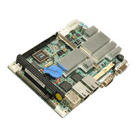
IEI Technology WAFER-LX3 User Manual (247 pages)
3.5" AMD Geode LX800 Motherboard with VGA, LVDS and TTL Monitor Capabilities, Dual LAN, USB 2.0, Audio and On-board Memory
Brand:
IEI Technology
| Category:
Motherboard
| Size: 10.06 MB
Table of Contents
Packing List
6
Table of Contents
7
Introduction
21
Overview
22
WAFER-LX3 Introduction
22
WAFER-LX3 Models
23
WAFER-LX3 Features
23
Figure 1-2: WAFER-LX3-800 and WAFER-LX3-800W Heat Sinks
23
Wafer-Lx3 Overview
24
WAFER-LX3 Overview Photo
24
Figure 1-3: WAFER-Lx3Overview [Front View]
25
WAFER-LX3 Peripheral Connectors and Jumpers
26
Figure 1-4: WAFER-LX3 Overview [Solder Side]
26
Technical Specifications
27
Table 1-1: Technical Specifications
29
Detailed Specifications
31
Dimensions
32
Board Dimensions
32
Figure 2-1: WAFER-LX3 Dimensions (MM)
32
External Interface Panel Dimensions
33
Figure 2-2: External Interface Panel Dimensions (MM)
33
Data Flow
34
Figure 2-3: Data Flow Block Diagram
34
Cpu Support
35
AMD Geode™ LX 800 500Mhz Overview
35
Figure 2-4: AMD ® Geode™ LX 800 Processor
35
AMD Geode™ LX 800 Memory Support
36
Figure 2-5: Four Memory Chipsets
36
AMD Geode™ LX 800 500Mhz Display Support
37
LVDS Interface
38
Figure 2-6: TFT and VGA Connector
38
Figure 2-7: LVDS Connector and Transmitter
38
AMD Geode™ LX 800 500Mhz Graphics Processor
39
Table 2-1: Geode LX Graphics Features
39
AMD Geode™ LX 800 500Mhz Power Management
40
Geodelink™ Interface Unit
41
AMD ® Geode™ CS5536 System Chipset
41
AMD Geode™ CS5536 ATA-6 Controller
41
Figure 1-1: WAFER-LX3 3.5" Motherboard
42
Figure 2-8: IDE Connector
42
Table 2-2: Supported HDD Specifications
42
AMD Geode™ CS5536 Audio Codec 97 (AC'97) Controller
43
Figure 2-9: Audio Connector and Codec
43
AMD Geode™ CS5536 Flash Interface
45
AMD Geode™ CS5536 USB Controller
45
Figure 2-10: CF Card Socket
45
AMD Geode™ CS5536 Real Time Clock
46
Geodelink™ PCI Bridge
46
Overview
46
Figure 2-11: USB Connectors
46
PCI Bridge Components
47
Intel® 82551ER PCI Ethernet Controller
47
Figure 2-12: Ethernet Controller
48
PCI to ISA Bridge
49
Figure 2-13: PCI-To-ISA Bridge
49
Lpc Bus Components
50
LPC Bus Overview
50
BIOS Chipset
50
Winbond W83627EHG Super I/O Chipset
51
Figure 2-14: BIOS Chipset
51
Figure 2-15: Super I/O Chipset
52
Super I/O Hardware Monitor Functions
52
Super I/O LPC Interface
52
Super I/O UART Controller
52
Super I/O Floppy Disk Drive (FDD) Controller
53
Super I/O Parallel Port
53
Super I/O Keyboard and Mouse Controller
54
Super I/O Fan Speed and Fan Control
55
Super I/O GPIO Ports
55
Environmental and Power Specifications
55
Operating Temperature and Temperature Control
55
Power Consumption
55
Table 2-3: Power Consumption
55
Unpacking
57
Anti-Static Precautions
58
Unpacking
58
Unpacking Precautions
58
Unpacking Checklist
59
Package Contents
59
Table 3-1: Package List Contents
60
Optional Items
61
Table 3-2: Package List Contents
61
Connector Pinouts
63
Peripheral Interface Connectors
64
WAFER-LX3 Layout
64
Figure 4-1: Connector and Jumper Locations
64
Peripheral Interface Connectors
65
Figure 4-2: Connector and Jumper Locations (Solder Side)
65
External Interface Panel Connectors
66
Table 4-1: Peripheral Interface Connectors
66
Table 4-2: Rear Panel Connectors
66
Internal Peripheral Connectors
67
ATX Power Button Connector
67
Figure 4-3: ATX Power Button Connector Location
67
Table 4-3: ATX Power Button Connector Pinouts
67
ATX Power Input Connector
68
Figure 4-4: Main Power Input Connector Location
68
Table 4-4: Main Power Input Connector Pinouts
68
ATX Power Supply Enable Connector
69
Figure 4-5: ATX Power Supply Enable Connector Location
69
Table 4-5: ATX Power Supply Enable Connector Pinouts
69
Audio Connector (10-Pin)
70
Figure 4-6: Audio Connector Pinouts (10-Pin)
70
Table 4-6: Audio Connector Pinouts (10-Pin)
70
Backlight Inverter Connector
71
Figure 4-7: Panel Backlight Connector Pinout Locations
71
Table 4-7: Panel Backlight Connector Pinouts
71
Battery Connector
72
Compactflash® Socket
72
Figure 4-8: Battery Connector Location
72
Table 4-8: Battery Connector Pinouts
72
Figure 4-9: CF Card Socket Location
74
Fan Connector (+12V, 3-Pin)
75
Table 4-9: CF Card Socket Pinouts
75
Floppy Disk Connector (26-Pin)
76
Figure 4-10: +5V Fan Connector Location
76
Table 4-10: +5V Fan Connector Pinouts
76
Figure 4-11: 26-Pin FDD Connector Location
77
GPIO Connector
78
Figure 4-12: GPIO Connector Pinout Locations
78
Table 4-11: 26-Pin FDD Connector Pinouts
78
Table 4-12: GPIO Connector Pinouts
78
HDD Connector(44-Pin)
79
Figure 4-13: Secondary IDE Device Connector Locations
79
Keyboard/Mouse Connector
80
Table 4-13: Secondary IDE Connector Pinouts
80
LCD LVDS Connector
81
Figure 4-14: Keyboard/Mouse Connector Location
81
Table 4-14: Keyboard/Mouse Connector Pinouts
81
Figure 4-15: TFT LCD LVDS Connector Pinout Locations
82
LED Connector
83
Figure 4-16: LED Connector Locations
83
Table 4-15: LCD LVDS Port Connector Pinouts
83
Print Connector
84
Figure 4-17: Parallel Port Connector Location
84
Table 4-16: LED Connector Pinouts
84
PC/104 Slot
85
Table 4-17: Parallel Port Connector Pinouts
85
Figure 4-18: PC/104 Slot Location
87
PC/104 Power Input Connector
89
Figure 4-19: PC/104 Power Input Connector Pinouts
89
Table 4-18: PC/104 Slot Connector Pinouts
89
Reset Button Connector
90
Figure 4-20: Reset Button Connector Locations
90
Table 4-19: PC/104 Power Input Connector Pinouts
90
Table 4-20: Reset Button Connector Pinouts
90
Serial Port Connector (COM 2)(RS-232, RS-422 or RS-485)
91
Figure 4-21: RS-232/422/485 Serial Port Connector Location
91
Table 4-21: RS-232/RS-485 Serial Port Connector Pinouts
91
TFT LCD Connector
92
Figure 4-22: TFT LCD Connector Pinout Locations
92
USB Connector (Internal)
93
Table 4-22: TFT LCD Port Connector Pinouts
93
External Peripheral Interface Connector Panel
94
Figure 4-23: USB Connector Pinout Locations
94
Table 4-23: USB Port Connector Pinouts
94
Figure 4-24: WAFER-LX3 External Peripheral Interface Connector
95
LAN Connectors
95
Table 4-24: LAN Pinouts
95
Figure 4-25: RJ-45 Ethernet Connector
96
Serial Port Connectors (COM1, COM3 and COM4)
96
Table 4-25: RJ-45 Ethernet Connector Leds
96
Figure 4-26: COM1 Pinout Locations
97
Table 4-26: RS-232 Serial Port (COM 1) Pinouts
97
USB Connector
97
Figure 4-27: VGA Connector
98
Table 4-27: USB Port Pinouts
98
VGA Connector
98
Table 4-28: VGA Connector Pinouts
99
Installation
101
Anti-Static Precautions
102
Installation Considerations
103
Installation Notices
103
Installation Checklist
104
Unpacking
105
Unpacking Precautions
105
CF Card Installation
105
Figure 5-1: CF Card Installation
106
Jumper Settings
107
Table 5-1: Jumpers
107
AT Power Select Jumper Settings
108
Figure 5-2: at Power Select Jumper Location
108
Table 5-2: at Power Select Jumper Settings
108
CF Card Setup
109
Clear CMOS Jumper
109
Figure 5-3: CF Card Setup Jumper Location
109
Table 5-3: CF Card Setup Jumper Settings
109
Table 5-4: CN7 Clear CMOS Jumper Settings
110
COM 1/2 Pin 9 Setting Jumper
111
Figure 5-4: Clear CMOS Jumper
111
Table 5-5: COM 1/2 Pin 9 Setting Jumper Settings
111
Figure 5-5: COM 1/2 Pin 9 Setting Jumper Location
112
LCD Panel Shift Clock Setting
112
Figure 5-6: LCD Panel Shift Clock Setting Jumper Location
113
LCD Voltage Selection
113
Table 5-6: LCD Panel Shift Clock Setting
113
Figure 5-7: LCD Voltage Selection Jumper Location
114
RS-422/485 Serial Port Select Jumper
114
Table 5-7: LCD Voltage Selection Jumper Settings
114
Chassis Installation
115
Airflow
115
Figure 5-8: Serial Port Mode Select Jumper Pinout Locations
115
Table 5-8: Serial Port Mode Select Jumper Settings
115
Internal Peripheral Device Connections
116
Peripheral Device Cables
116
ATA Flat Cable Connection
116
Table 5-9: IEI Provided Cables
116
Keyboard/Mouse Y-Cable Connector
117
Figure 5-9: IDE Cable Connection
117
Figure 5-10: Keyboard/Mouse Y-Cable Connection
118
Parallel Port Cable Without Bracket
119
Figure 5-11: LPT Cable Connection
119
Dual RS-232 Cable Connection (W/O Bracket)
120
Figure 5-12: Connect the LPT Device
120
USB Cable (Dual Port Without Bracket)
121
Figure 5-13: Dual RS-232/422/485 Cable Installation
121
External Peripheral Interface Connection
122
Figure 5-14: Dual USB Cable Connection
122
Figure 5-15: LAN Connection
123
LAN Connection (Single Connector)
123
Figure 5-16: Serial Device Connector
124
Serial Device Connection
124
Figure 5-17: USB Device Connection
125
USB Device Connection (Single Connector)
125
Figure 5-18: VGA Connector
126
VGA Monitor Connection
126
Bios Screens
127
Introduction
128
Starting Setup
128
Using Setup
128
Getting Help
129
Unable to Reboot after Configuration Changes
129
Main BIOS Menu
129
Table 6-1: BIOS Navigation Keys
129
BIOS Menu 1: Award BIOS CMOS Setup Utility
130
Standard Cmos Features
132
BIOS Menu 2: Standard CMOS Features
132
IDE Primary Master/Slave
135
BIOS Menu 3: IDE Primary Master/Slave Menu
135
Advanced Bios Features
138
BIOS Menu 4: Advanced BIOS Features
138
Advanced Chipset Features
141
BIOS Menu 5: Advanced Chipset Features
141
Flat Panel Configuration
144
BIOS Menu 6: Flat Panel Configuration
144
Integrated Peripherals
147
BIOS Menu 7: Integrated Peripherals
147
IT8888 ISA Decode IO
152
BIOS Menu 8: IT8888 ISA Decode IO
152
IT8888 ISA Decode Memory
154
BIOS Menu 9: IT8888 ISA Decode Memory
155
Power Management Setup
157
BIOS Menu 10: Power Management Setup
157
Pnp/Pci Configurations
160
BIOS Menu 11: IRQ Wakeup Events
160
BIOS Menu 12: Pnp/Pci Configurations
161
BIOS Menu 13: IRQ Resources
162
BIOS Menu 14: Memory Resources
163
Pc Health Status
164
BIOS Menu 15: PC Health Status
165
Software Drivers
167
Available Software Drivers
168
Open the Device Manager in Windows
168
Figure 7-1: Access Windows Control Panel
169
Figure 7-2: Performance and Maintenance
170
Figure 7-3: Access the System
170
Figure 7-4: System Properties
171
Figure 7-5: Open Device Manager
172
Vga Driver Installation
173
Figure 7-6: Device Manager
173
Figure 7-7: Video Controller (Device Manager)
174
Figure 7-8: Update Driver Selection
174
Figure 7-9: Hardware Update Wizard
175
Figure 7-10: VGA Driver Installation Start
176
Figure 7-11: Wizard Search
177
Figure 7-12: Wizard Warning Screen
177
Figure 7-13: VGA Driver Installation
178
Figure 7-14: VGA Driver Installation Complete
179
Audio Driver Installation
180
Figure 7-15: Device Manager Update
180
Figure 7-16: Audio Controller (Device Manager)
181
Figure 7-17: Update Audio Driver Selection
181
Figure 7-18: Hardware Update Wizard
182
Figure 7-19: Audio Driver Installation Start
183
Figure 7-20: Wizard Search
184
Figure 7-21: Wizard Warning Screen
184
Figure 7-22: Audio Driver Installation
185
Figure 7-23: Audio Driver Installation Complete
186
Ethernet Driver Installation
187
Figure 7-24: Device Manager Update
187
Figure 7-25: Ethernet Controller (Device Manager)
188
Figure 7-26: Update Ethernet Driver Selection
188
Figure 7-27: Hardware Update Wizard
189
Figure 7-28: Ethernet Driver Installation Start
190
Figure 7-29: Wizard Search
191
Figure 7-30: Wizard Warning Screen
191
Figure 7-31: Ethernet Driver Installation
192
Figure 7-32: Ethernet Driver Installation Complete
193
Entertainment Encryption/Decryption Controller
194
Figure 7-33: Device Manager Update
194
Figure 7-34: Entertainment Encryption/Decryption Controller (Device Manager)
195
Figure 7-35: Update Entertainment Encryption/Decryption Controller Driver Selection
195
Figure 7-36: Hardware Update Wizard
196
Figure 7-37: Entertainment Encryption/Decryption Controller Driver Installation Start
197
Figure 7-38: Wizard Search
198
Figure 7-39: Entertainment Encryption/Decryption Controller Driver Installation
199
Figure 7-40: Entertainment Encryption/Decryption Controller Driver Complete
200
Other Pci Bridge Device Controller
201
Figure 7-41: Device Manager Update
201
Figure 7-42: Other PCI Bridge Device Controller (Device Manager)
202
Figure 7-43: Other PCI Bridge Device Controller Driver Selection
203
Figure 7-44: Hardware Update Wizard
204
Figure 7-45: Other PCI Bridge Device Controller Driver Installation Start
205
Figure 7-46: Wizard Search
206
Figure 7-47: Other PCI Bridge Device Controller Driver Installation Complete
207
Figure 7-48: Device Manager Update
208
Abios Options
209
Bterminology
213
Cdio Interface
217
Dio Interface Introduction
218
Dio Connector Pinouts
218
Assembly Language Samples
219
Enable the DIO Input Function
219
Enable the DIO Output Function
219
Dwatchdog Timer
221
Eaddress Mapping
225
Address Map
226
St Mb Memory Address Map
226
Irq Mapping Table
227
Dma Channel Assignments
227
Fcompatibility
229
Compatible Operating Systems
230
Ghazardous Materials Disclosure
231
Ercury
232
Haudio Codec Configuration
235
Introduction
236
Accessing the AC'97 CODEC
236
Driver Installation
236
H.1 I Ntroduction
236
Sound Effect Configuration
237
Accessing the Sound Effects Manager
237
H.2 S OUND E FFECT C ONFIGURATION H.2.1 Accessing the Sound Effects Manager
237
Sound Effect Manager Configuration Options
238
Index
241
Advertisement
IEI Technology WAFER-LX3 User Manual (229 pages)
3.5'' ETX Motherboard with AMD Geode LX 800 CPU VGA, LVDS, TTL, Dual LAN, USB 2.0, Audio, PC/104 Fanless and Onboard Memory
Brand:
IEI Technology
| Category:
Motherboard
| Size: 8.8 MB
Table of Contents
User Manual
1
Packing List
4
Table of Contents
5
1 Introduction
19
Introduction
20
Models
20
Features
21
Overview
21
Figure 1-2: WAFER-LX3-800 and WAFER-LX3-800 W
21
Figure 1-3: WAFER-LX3 Overview [Front View]
22
Peripheral Connectors and Jumpers
23
Figure 1-4: WAFER-LX3 Overview [Solder Side]
23
Technical Specifications
24
Table 1-1: Technical Specifications
26
2 Detailed Specifications
27
Dimensions
28
Figure 2-1: WAFER-LX3 Dimensions (Front) (MM)
28
Figure 2-2: WAFER-LX3 Dimensions (Solder Side) (MM)
28
Data Flow
29
Figure 2-3: External Interface Panel Dimensions (MM)
29
AMD ® Geode™ LX 800 500 Mhz CPU
30
Figure 2-4: Data Flow Block Diagram
30
Figure 2-5: AMD Geode™ LX 800 Processor
31
Memory Support
31
Display Support
32
Vga
32
Ttl
32
Lvds
32
Power Management
32
Geodelink™ Interface Unit
33
AMD ® Geode™ CS5536 System Chipset
33
Figure 2-6: AMD Geode™ CS5536
33
Audio Codec 97 (AC'97) Controller
34
Flash Interface
34
IDE Controller
34
PCI Bus
34
Intel® 82551ER PCI Ethernet Controller
35
PCI to ISA Bridge
35
Real Time Clock
34
USB Controller
34
Lpc Bus Components
35
Figure 2-7: LPC Bus
35
BIOS Chipset
36
SMSC SCH3114 Super I/O Chipset
36
Hardware Monitor Functions
36
UART Controller
36
Parallel Port
37
Floppy Disk Drive Controller (Optional)
37
Keyboard and Mouse Controller
37
GPIO Ports
37
Fan Speed and Fan Control
38
Environmental and Power Specifications
38
Operating Temperature and Temperature Control
38
Power Consumption
38
Table 2-1: Power Consumption
38
3 Unpacking
39
Anti-Static Precautions
40
Unpacking
40
Unpacking Precautions
40
Unpacking Checklist
41
Package Contents
41
Optional Items
42
Table 3-1: Package List Contents
42
Table 3-2: Package List Contents
42
4 Connector Pinouts
43
Peripheral Interface Connectors
44
Layout
44
Figure 4-1: Connector and Jumper Locations
44
Peripheral Interface Connectors
45
Figure 4-2: Connector and Jumper Locations (Solder Side)
45
External Interface Panel Connectors
46
Table 4-1: Peripheral Interface Connectors
46
Table 4-2: Rear Panel Connectors
46
Internal Peripheral Connectors
47
ATX Power Button Connector
47
ATX Power Input Connector
47
Figure 4-3: ATX Power Button Connector Location
47
Table 4-3: ATX Power Button Connector Pinouts
47
ATX Power Supply Enable Connector
48
Figure 4-4: Main Power Input Connector Location
48
Table 4-4: Main Power Input Connector Pinouts
48
Audio Connector (10-Pin)
49
Figure 4-5: ATX Power Supply Enable Connector Location
49
Table 4-5: ATX Power Supply Enable Connector Pinouts
49
Backlight Inverter Connector
50
Figure 1-1: WAFER-LX3
50
Figure 4-6: Audio Connector Pinouts (10-Pin)
50
Table 4-6: Audio Connector Pinouts (10-Pin)
50
Battery Connector
51
Figure 4-7: Panel Backlight Connector Pinout Locations
51
Table 4-7: Panel Backlight Connector Pinouts
51
Compactflash® Socket
52
Figure 4-8: Battery Connector Location
52
Table 4-8: Battery Connector Pinouts
52
Figure 4-9: CF Card Socket Location
53
Fan Connector (+5 V, 3-Pin)
54
Figure 4-10: +5 V Fan Connector Location
54
Table 4-9: CF Card Socket Pinouts
54
Floppy Disk Connector (26-Pin)
55
Figure 4-11: 26-Pin FDD Connector Location
55
Table 4-10: +5 V Fan Connector Pinouts
55
GPIO Connector
56
Figure 4-12: GPIO Connector Pinout Locations
56
Table 4-11: 26-Pin FDD Connector Pinouts
56
HDD Connector(44-Pin)
57
Figure 4-13: Secondary IDE Device Connector Locations
57
Table 4-12: GPIO Connector Pinouts
57
Keyboard/Mouse Connector
58
Table 4-13: Secondary IDE Connector Pinouts
58
LCD LVDS Connector
59
Figure 4-14: Keyboard/Mouse Connector Location
59
Table 4-14: Keyboard/Mouse Connector Pinouts
59
LED Connector
60
Figure 4-15: TFT LCD LVDS Connector Pinout Locations
60
Table 4-15: LCD LVDS Port Connector Pinouts
60
Print Connector
61
Figure 4-16: LED Connector Locations
61
Table 4-16: LED Connector Pinouts
61
PC/104 Slot
62
Figure 4-17: Parallel Port Connector Location
62
Table 4-17: Parallel Port Connector Pinouts
62
Figure 4-18: PC/104 Slot Location
63
PC/104 Power Input Connector
64
Table 4-18: PC/104 Slot Connector Pinouts
64
Reset Button Connector
65
Figure 4-19: PC/104 Power Input Connector Pinouts
65
Table 4-19: PC/104 Power Input Connector Pinouts
65
Serial Port Connector (COM3)
66
Figure 4-20: Reset Button Connector Locations
66
Figure 4-21: Serial Port Connector Location
66
Table 4-20: Reset Button Connector Pinouts
66
Serial Port Connector (COM2:RS-232, COM4:RS-422/485)
67
Figure 4-22: RS-232 and RS-422/485 Serial Port Connector Location
67
Table 4-21: COM3 Pinouts
67
TFT LCD Connector
68
Figure 4-23: TFT LCD Connector Pinout Locations
68
Table 4-22: COM2 Pinouts
68
Table 4-23: COM4 Pinouts
68
USB Connector (Internal)
69
Table 4-24: TFT LCD Port Connector Pinouts
69
External Peripheral Interface Connector Panel
70
Figure 4-24: USB Connector Pinout Locations
70
Table 4-25: USB Port Connector Pinouts
70
Figure 4-25: WAFER-LX3 External Peripheral Interface Connector
71
Figure 4-26: RJ-45 Ethernet Connector
71
LAN Connectors
71
Table 4-26: LAN Pinouts
71
Figure 4-27: COM1 Pinout Locations
72
Serial Port Connector
72
Table 4-27: RJ-45 Ethernet Connector Leds
72
Table 4-28: RS-232 Serial Port (COM 1) Pinouts
72
Figure 4-28: VGA Connector
73
Table 4-29: USB Port Pinouts
73
USB Connector
73
VGA Connector
73
Table 4-30: VGA Connector Pinouts
74
5 Installation
75
Anti-Static Precautions
76
Installation Considerations
77
Installation Notices
77
Installation Checklist
78
Unpacking
79
Unpacking Precautions
79
CF Card Installation
79
Figure 5-1: CF Card Installation
80
Jumper Settings
81
AT Power Select Jumper Settings
81
Table 5-1: Jumpers
81
CF Card Setup
82
Figure 5-2: at Power Select Jumper Location
82
Table 5-2: at Power Select Jumper Settings
82
Clear CMOS
83
Figure 5-3: CF Card Setup Jumper Location
83
Table 5-3: CF Card Setup Jumper Settings
83
COM 1/2 Pin 9 Setting Jumper
84
Figure 5-4: Clear CMOS Jumper
84
Table 5-4: CN7 Clear CMOS Jumper Settings
84
LCD Panel Shift Clock Setting
85
Figure 5-5: COM 1/2 Pin 9 Setting Jumper Location
85
Table 5-5: COM 1/2 Pin 9 Setting Jumper Settings
85
LCD Voltage Selection
86
Figure 5-6: LCD Panel Shift Clock Setting Jumper Location
86
Table 5-6: LCD Panel Shift Clock Setting
86
RS-422/485 Serial Port Select Jumper
87
Figure 5-7: LCD Voltage Selection Jumper Location
87
Table 5-7: LCD Voltage Selection Jumper Settings
87
Chassis Installation
88
Airflow
88
Figure 5-8: Serial Port Mode Select Jumper Pinout Locations
88
Table 5-8: Serial Port Mode Select Jumper Settings
88
Internal Peripheral Device Connections
89
Peripheral Device Cables
89
ATA Flat Cable Connection
89
Table 5-9: IEI Provided Cables
89
Keyboard/Mouse Y-Cable Connector
90
Figure 5-9: IDE Cable Connection
90
Figure 5-10: Keyboard/Mouse Y-Cable Connection
91
Parallel Port Cable Without Bracket
92
Figure 5-11: LPT Cable Connection
92
Dual RS-232 Cable Connection (W/O Bracket)
93
Figure 5-12: Connect the LPT Device
93
USB Cable (Dual Port Without Bracket)
94
Figure 5-13: Dual RS-232 Cable Installation
94
External Peripheral Interface Connection
95
Figure 5-14: Dual USB Cable Connection
95
Figure 5-15: LAN Connection
96
LAN Connection (Single Connector)
96
Serial Device Connection
96
Figure 5-16: Serial Device Connector
97
USB Device Connection (Single Connector)
97
Figure 5-17: USB Device Connection
98
VGA Monitor Connection
98
Figure 5-18: VGA Connector
99
6 Bios
100
Introduction
101
Starting Setup
101
Using Setup
101
Getting Help
102
Unable to Reboot after Configuration Changes
102
BIOS Menu Bar
102
Table 6-1: BIOS Navigation Keys
102
Main
103
BIOS Menu 1: Main
103
Advanced
104
BIOS Menu 2: Advanced
105
CPU Configuration
106
BIOS Menu 3: CPU Configuration
106
IDE Configuration
107
BIOS Menu 4: IDE Configuration
107
IDE Master, IDE Slave
109
BIOS Menu 5: IDE Master and IDE Slave Configuration
109
Floppy Configuration
114
BIOS Menu 6: IDE Master and IDE Slave Configuration
114
Super IO Configuration
115
BIOS Menu 7: Super IO Configuration
115
Hardware Health Configuration
118
BIOS Menu 8: Hardware Health Configuration
118
Remote Configuration
122
BIOS Menu 9: Remote Access Configuration
122
USB Configuration
126
BIOS Menu 10: USB Configuration
126
IT8888 Configuration
127
BIOS Menu 11: IT8888 Configuration
127
ISA Decode IO Spaces
132
BIOS Menu 12: ISA Decode I/O Spaces
132
ISA Decode Memory Spaces
134
BIOS Menu 13: ISA Decode Memory Spaces
134
Power Configuration
136
Pci/Pnp
136
BIOS Menu 14: Power Configuration
136
BIOS Menu 15: Pci/Pnp Configuration
137
Boot
139
BIOS Menu 16: Boot
139
Boot Settings Configuration
140
BIOS Menu 17: Boot Settings Configuration
140
Boot Device Priority
141
Hard Disk Drives
142
BIOS Menu 18: Boot Device Priority Settings
142
CD/DVD Drives
143
BIOS Menu 19: Hard Disk Drives
143
Removable Drives
144
BIOS Menu 20: CD/DVD Drives
144
BIOS Menu 21: Removable Drives
145
Security
146
BIOS Menu 22: Security
146
Chipset
147
BIOS Menu 23: Chipset
147
Video Configuration
148
BIOS Menu 24: Northbridge Chipset Configuration
148
Exit
150
BIOS Menu 25: Exit
150
7 Driver Installation
152
Available Software Drivers
153
Open the Device Manager in Windows
153
Figure 7-1: Access Windows Control Panel
154
Figure 7-2: Performance and Maintenance
155
Figure 7-3: Access the System
155
Figure 7-4: System Properties
156
Figure 7-5: Open Device Manager
157
Vga Driver Installation
158
Figure 7-6: Device Manager
158
Figure 7-7: Video Controller (Device Manager)
159
Figure 7-8: Update Driver Selection
159
Figure 7-9: Hardware Update Wizard
160
Figure 7-10: VGA Driver Installation Start
161
Figure 7-11: Wizard Search
162
Figure 7-12: Wizard Warning Screen
162
Figure 7-13: VGA Driver Installation
163
Figure 7-14: VGA Driver Installation Complete
164
Audio Driver Installation
165
Figure 7-15: Device Manager Update
165
Figure 7-16: Audio Controller (Device Manager)
166
Figure 7-17: Update Audio Driver Selection
166
Figure 7-18: Hardware Update Wizard
167
Figure 7-19: Audio Driver Installation Start
168
Figure 7-20: Wizard Search
169
Figure 7-21: Wizard Warning Screen
169
Figure 7-22: Audio Driver Installation
170
Figure 7-23: Audio Driver Installation Complete
171
Ethernet Driver Installation
172
Figure 7-24: Device Manager Update
172
Figure 7-25: Ethernet Controller (Device Manager)
173
Figure 7-26: Update Ethernet Driver Selection
173
Figure 7-27: Hardware Update Wizard
174
Figure 7-28: Ethernet Driver Installation Start
175
Figure 7-29: Wizard Search
176
Figure 7-30: Wizard Warning Screen
176
Figure 7-31: Ethernet Driver Installation
177
Figure 7-32: Ethernet Driver Installation Complete
178
Entertainment Encryption/Decryption Controller
179
Figure 7-33: Device Manager Update
179
Figure 7-34: Entertainment Encryption/Decryption Controller
180
Figure 7-35: Update Entertainment Encryption/Decryption Controller
180
Figure 7-36: Hardware Update Wizard
181
Figure 7-37: Entertainment Encryption/Decryption Controller Driver
182
Figure 7-38: Wizard Search
183
Figure 7-39: Entertainment Encryption/Decryption Controller Installation
184
Figure 7-40: Entertainment Encryption/Decryption Controller Installation Complete
185
Other Pci Bridge Device Controller
186
Figure 7-41: Device Manager Update
186
Figure 7-42: Other PCI Bridge Device Controller (Device Manager)
187
Figure 7-43: Other PCI Bridge Device Controller Driver Selection
188
Figure 7-44: Hardware Update Wizard
189
Figure 7-45: Other PCI Bridge Device Controller Driver Installation Start
190
Figure 7-46: Wizard Search
191
Figure 7-47: PCI Bridge Device Controller Driver Installation Complete
192
Figure 7-48: Device Manager Update
193
ABIOS Options
194
B Terminology
198
C Digital I/O Interface
202
Introduction
203
Dio Connector Pinouts
203
C.1 I Ntroduction
203
Assembly Language Samples
204
Enable the DIO Input Function
204
Enable the DIO Output Function
204
D Watchdog Timer
205
E Address Mapping
208
Address Map
209
St Mb Memory Address Map
209
E.1 Addres Map
209
Irq Mapping Table
210
Dma Channel Assignments
210
F Compatibility
211
Compatible Operating Systems
212
G Hazardous Materials Disclosure
213
Hazardous Materials Disclosure Table for IPB Products Certified as Rohs Compliant under 2002/95/EC Without Mercury
214
H Ac'97 Audio Codec
217
Introduction
218
Accessing the AC'97 CODEC
218
Driver Installation
218
H.1 I Ntroduction
218
Sound Effect Configuration
219
Accessing the Sound Effects Manager
219
Sound Effect Manager Configuration Options
220
Advertisement
Related Products
IEI Technology WAFER-LX3-800
IEI Technology WAFER-LX3-800W
IEI Technology WAFER-LX
IEI Technology WAFER-LX2-800
IEI Technology WAFER-LX-800-R12
IEI Technology WAFER-LX-WINXPE
IEI Technology WAFER-LX-CLIENT-XPE
IEI Technology WAFER-LX-CLIENT-CENET050
IEI Technology WAFER-LX-800-R10
IEI Technology WAFER-LX Series
IEI Technology Categories
Motherboard
Touch Panel
Computer Hardware
Single board computers
Desktop
More IEI Technology Manuals
Login
Sign In
OR
Sign in with Facebook
Sign in with Google
Upload manual
Upload from disk
Upload from URL