Sign In
Upload
Manuals
Brands
IEI Technology Manuals
Touch Panel
UPC-12A/GM45
IEI Technology UPC-12A/GM45 Manuals
Manuals and User Guides for IEI Technology UPC-12A/GM45. We have
1
IEI Technology UPC-12A/GM45 manual available for free PDF download: User Manual
IEI Technology UPC-12A/GM45 User Manual (145 pages)
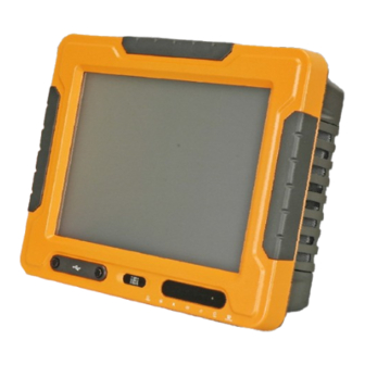
Touch Screen and Intel Core 2 Duo or Celeron M CPU, Gigabit Ethernet, Six USB, Audio, RS-232/422/485, SATA, RoHS Compliant, IP 65 Protection
Brand:
IEI Technology
| Category:
Touch Panel
| Size: 5 MB
Table of Contents
Table of Contents
4
Introduction
13
Upc-12A/Gm45 Panel Pc Overview
14
Model Variations
15
Features
15
Table 1-1: Model Variations
15
External Overview
16
Front Panel
16
Figure 1-2: Front View
16
Bottom Panel
17
Table 1-2: LCD Front LED Indicators
17
Figure 1-3: UPC-12A/GM45 Bottom View
18
Side Panels
19
Rear Panel
19
Figure 1-4: UPC-12A/GM45 Side View
19
Figure 1-5: UPC-12A/GM45 Rear View
19
Frame
20
Specifications
20
Preinstalled Hardware Components
20
System Specifications
20
Table 1-3: UPC-12A/GM45 System Specifications
23
Detailed Specifications
24
Dimensions
25
F Igure 2-1: UPC-12A/GM45 Dimensions
25
Intel ® Processor Support
26
Figure 2-2: CPU and Chipsets Heat Sink
26
Table 2-1: UPC-12A/GM45 Series CPU Specifications
26
Motherboard Components
27
Memory Support
27
Installed Memory
27
Additional Memory
27
Storage Capacity
27
Figure 2-3: Memory Module and Memory Socket
27
External Peripheral Interface Connectors
28
Serial Port Connectors
28
Figure 2-4: SATA Hard Disk Drive Bay
28
Figure 2-5: Compactflash® Slot
28
LAN Connectivity
29
Figure 2-6: COM Ports
29
Figure 2-7: RJ-45 Ethernet Connector
29
External USB Connectors
30
Upc-12A/Gm45 Front Side
30
Monitor
30
Touch-Screen Module
30
Figure 2-8: External Standard USB Ports
30
OSD Buttons
31
Figure 2-9: OSD Buttons
31
Graphics
32
Figure 2-11: Audio Connectors
32
Figure 2-12: Power Connectors
34
Figure 2-13: Lithium Battery Pack
34
Figure 2-14: AT/ATX Mode Switch
35
Figure 2-15: Ups/Battery Mode Switch
35
Table 2-2: at Power Mode
36
Table 2-3: ATX Power Mode
37
Figure 2-16: Wireless LAN Pcie Mini Card
38
Table 2-4: Buzzer Alarm
38
Wireless Ethernet
38
Installation Precautions
44
Figure 4-1: CF Card Installation
46
Hdd Installation
46
Figure 4-2: Hdd/Battery Access Panel Retention Screws
47
Figure 4-3: HDD Bracket Retention Screws
47
Figure 4-4: Secure the HDD with the HDD Bracket
48
Figure 4-5: HDD Installation
48
Figure 4-6: Hdd/Battery Access Panel Retention Screws
49
Battery Installation
49
Figure 4-7: Battery Installation
50
Figure 4-8: PCI Card Slot Cover Retention Screws
50
Figure 4-9: Jumper Locations
51
Table 4-1: Jumpers
51
Jumper Settings
51
F Igure 1-1: UPC-12A/GM45 Panel PC
52
T Able 4-2: Preconfigured Jumpers
52
T Able 4-3: CF Voltage Select Jumper Settings
52
Figure 4-10: CF Voltage Select Jumper Location
53
Table 4-4: CF Card Setup Jumper Settings
53
Figure 4-11: CF Card Setup Jumper Location
54
Figure 4-12: COM4 Function Select Jumper Locations
55
Table 4-5: COM4 Function Select Jumper Settings (JP4)
55
Table 4-6: COM4 Function Select Jumper Settings (JP5)
55
Table 4-7: RS-422 Pinouts
56
Table 4-8: RS-485 Pinouts
56
Figure 4-13: Clear CMOS Button
57
Figure 4-14: Wall-Mounting Bracket
58
Figure 4-15: Mount the Chassis
59
Figure 4-16: Secure the Chassis
60
F Igure 4-17: Suggested Panel Cut out Size for UPC-12A/GM45 (Unit
61
Figure 4-18: Panel Mounting Clamp Slots (Side View)
61
Figure 4-19: Tighten the Panel Mounting Clamp Screws
62
Figure 4-20: Arm Mounting Retention Screw Holes
63
Figure 4-21: AT/ATX Switch
64
Figure 4-22: LAN Connection
64
Figure 4-23: Serial Device Connector
65
Figure 4-24: USB Device Connection
66
System Maintenance
68
Replacing Components
70
Turn off the Power
70
Figure 5-1: Rear Cover Retention Screws
71
Figure 5-2: Wireless Module Location
72
Figure 5-3: SO-DIMM Socket Location
73
Figure 5-4: Installing a SO-DIMM
73
Figure 5-5: Gasket Replacement
74
Ami Bios Setup
76
Table 6-1: BIOS Navigation Keys
78
Figure 7-1: Welcome Screen
112
Figure 7-2: Select Installation Folder
113
Figure 7-3: Ready to Install the Program
113
Figure 7-4: Installing AUPS
114
Figure 7-5: Installation Complete
114
Figure 7-6: AUPS Battery Status Monitor Application
114
Figure 7-7: Status Information
115
Figure 7-8: DC Detection
115
Figure 7-9: Battery Detection
116
Figure 7-10: Total Battery Time
117
Figure 7-11: Battery Information
117
Figure 7-12: LAN Setting
118
Figure 7-13: LAN Setting - Change Password
119
Figure 7-14: Application Setting
120
Figure 7-15: COM Port Status
120
Figure 7-16: RJ-45 Remote LAN Connector
121
F Igure 7-17: IEI REMOTE
122
Figure 7-18: IEI REMOTE AP - IP Address
123
Figure 7-19: Remote Management Web Interface - Status
123
Figure 7-20: Remote Management Web Interface - H/W Monitor
124
Figure 7-21: Remote Management Web Interface - Send Email
125
Figure 7-22: Enter User Name and Password
125
Figure 7-23: Board Configuration
126
Safety Precautions
131
Watchdog Timer
139
Example Program
141
Advertisement
Advertisement
Related Products
IEI Technology UPC-V315-QM77
IEI Technology UPC-F12C-ULT3
IEI Technology UPC-F12M1-RPLP
IEI Technology uIBX-200-VX800
IEI Technology UPC-V312-D525
IEI Technology uIBX-230-BT Series
IEI Technology uIBX-210-CV-N2600 Series
IEI Technology uSmart3400
IEI Technology uIBX-260-EHL Series
IEI Technology 210UPC-V312
IEI Technology Categories
Motherboard
Touch Panel
Computer Hardware
Single board computers
Desktop
More IEI Technology Manuals
Login
Sign In
OR
Sign in with Facebook
Sign in with Google
Upload manual
Upload from disk
Upload from URL