Sign In
Upload
Manuals
Brands
IEI Technology Manuals
Touch Panel
PPC-F06B-BT
IEI Technology PPC-F06B-BT VGA Panel PC Manuals
Manuals and User Guides for IEI Technology PPC-F06B-BT VGA Panel PC. We have
1
IEI Technology PPC-F06B-BT VGA Panel PC manual available for free PDF download: User Manual
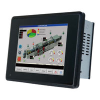
IEI Technology PPC-F06B-BT User Manual (112 pages)
Brand:
IEI Technology
| Category:
Touch Panel
| Size: 2 MB
Table of Contents
Table of Contents
5
1 Introduction
13
Overview
14
Figure 1-1: PPC-F06B-BT Series Panel PC
14
Features
15
Front Panel
15
Figure 1-2: Front View
15
Rear Panel
16
Side Panels
16
Figure 1-3: Rear View
16
Figure 1-4: Side View
16
Bottom Panel
17
Figure 1-5: Bottom Panel
17
Dimensions
18
Figure 1-6: PPC-F06B-BT Dimensions (MM)
18
Specifications
19
Table 1-1: System Specifications
20
2 Unpacking
21
Unpacking
22
Packing List
22
Table 2-1: Packing List
23
Optional Items
24
Table 2-2: Optional Items
24
3 Installation
25
Anti-Static Precautions
26
Installation Precautions
26
Preinstalled Components
27
Installation and Configuration Steps
27
Removing the
28
Sata Dom Installation
28
Figure 3-1: Back Cover Retention Screws
28
Figure 3-2: SATA Connector Location
29
Figure 3-3: SATA DOM Installation
29
Msata Module Installation
30
Figure 3-4: Msata Module Slot Location
30
Wireless LAN Module Installation (Optional)
31
Figure 3-5: Msata Module Installation
31
Figure 3-6: Knockout for Wireless Antenna (Left Side Panel)
31
Figure 3-7: Pcie Mini Slot Location
32
Figure 3-8: Removing Screw and Standoff
32
Figure 3-9: Installing the Standoff
33
Figure 3-10: Inserting the WLAN Module
33
Figure 3-11: Securing WLAN Module
34
Figure 3-12: Connecting RF Cables
34
Figure 3-13: Securing SMA Connector and External Antenna Installation
35
Serial Port Configuration and Connection
36
Serial Port Pinouts (COM1)
36
Serial Port Pin 9 Selection
36
Table 3-1: RS-232 Serial Port (COM1) Pinouts
36
Figure 3-14: Serial Port Locations
36
Table 3-2: COM1 Serial Port Pin 9 Setting Jumper Settings
37
Table 3-3: RS-422/485 Serial Port Pinouts
37
At/Atx Mode Selection
38
AT Power Mode
38
ATX Power Mode
38
Figure 3-15: COM1 Serial Port Pin 9 Setting Jumper Location
37
RS-422/485 Serial Port Pinouts (COM2)
37
Figure 3-16: AT/ATX Mode Selection
38
Mounting the System
39
Wall Mounting
39
Figure 3-17: Attach Wall Mounting Kit to the Wall
39
Figure 3-18: Hook Onto Wall Mounting Kit
40
Figure 3-19: Tighten Retention Screw
41
Panel Mounting
41
Figure 3-20: Panel Cutout Dimensions
42
Figure 3-21: Tighten the Mounting Clamp Screws
42
Figure 3-22: the Rack/Cabinet Bracket
43
Rack Mounting
43
Figure 3-23: Secure the Rack/Cabinet Bracket
44
Figure 3-24: Install into a Rack/Cabinet
44
Arm Mounting
45
Figure 3-25: Arm Mounting (ARM-11-RS)
46
Stand Mounting
46
Figure 3-26: Stand Mounting (Stand-B08)
47
Figure 3-27: Powering on the System
47
Powering on the System
47
Clear Cmos
48
Figure 3-28: Reset Button Location
48
Figure 3-29: Clear CMOS Button Location
48
Reset the System
48
Driver Installation
49
Figure 3-30: BIOS Option-OS Selection
49
Keypad AP
50
Figure 3-31: Keypad AP
50
Os Installation
49
System Maintenance
51
4 Bios Setup
52
Introduction
53
Starting Setup
53
Using Setup
53
Getting Help
54
Unable to Reboot after Configuration Changes
54
Table 4-1: BIOS Navigation Keys
54
BIOS Menu 1: Main
55
BIOS Information
56
CPU Information
56
Memory Information
56
TXE Information
56
System Date [XX/XX/XX]
56
Advanced
57
System Time [XX:XX:XX]
57
ACPI Settings
58
BIOS Menu Bar
55
Main
55
BIOS Menu 2: Advanced
58
BIOS Menu 3: ACPI Settings
58
F81866 Super IO Configuration
59
BIOS Menu 4: F81866 Super IO Configuration
59
ACPI Sleep State [S3 (Suspend to RAM)]
59
Serial Port N Configuration
60
BIOS Menu 5: Serial Port N Configuration Menu
60
Serial Port [Enabled]
60
Change Settings [Auto]
60
Serial Port [Enabled]
61
Change Settings [Auto]
61
F81866 H/W Monitor
62
BIOS Menu 6: F81866 H/W Monitor
62
Hardware Health Status
62
RTC Wake Settings
63
BIOS Menu 7: RTC Wake Settings
63
Wake System with Fixed Time [Disabled]
63
Serial Port Console Redirection
64
BIOS Menu 8: Serial Port Console Redirection
64
IEI Feature
65
BIOS Menu 9: IEI Feature
65
Console Redirection [Disabled]
65
Auto Recovery Function [Disabled]
65
CPU Configuration
66
BIOS Menu 10: CPU Configuration
66
Intel Virtualization [Disabled]
67
EIST [Enabled]
67
IDE Configuration
68
BIOS Menu 11: IDE Configuration
68
Serial-ATA (SATA) [Enabled]
68
SATA Mode [IDE Mode]
68
USB Configuration
69
BIOS Menu 12: USB Configuration
69
USB Devices
69
Legacy USB Support [Enabled]
69
Chipset
70
BIOS Menu 13: Chipset
70
North Bridge Configuration
71
Internal IGD Configuration
71
BIOS Menu 14: North Bridge Configuration
71
BIOS Menu 15: Internal IGD Configuration
71
DVMT Pre-Allocated [256M]
72
DVMT Total Gfx Mem [Max]
72
South Bridge Configuration
73
BIOS Menu 16: South Bridge Configuration
73
Restore on AC Power Loss [Last State]
73
Audio Controller [Enabled]
73
Security
74
BIOS Menu 17: Security
74
Administrator Password
74
User Password
74
Boot
75
BIOS Menu 18: Boot
75
Bootup Numlock State [On]
75
Quiet Boot [Enabled]
76
UEFI Boot [Disabled]
76
OS Selection [Windows 8.X]
76
Launch PXE Oprom [Disabled]
77
Option ROM Messages [Force BIOS]
77
Save & Exit
78
BIOS Menu 19: Save & Exit
78
Save Changes and Reset
78
Discard Changes and Reset
78
Restore Defaults
78
Save as User Defaults
79
Restore User Defaults
79
5 Interface Connectors
80
Peripheral Interface Connectors
81
Figure 5-1: Main Board Layout Diagram (Front Side)
81
Internal Peripheral Connectors
82
Figure 5-2: Main Board Layout Diagram (Solder Side)
82
Audio Connector (AUDIO1)
83
Battery Connector (BAT2)
83
Table 5-1: Peripheral Interface Connectors
83
Table 5-2: Audio Connector (AUDIO1) Pinouts
83
Table 5-3: Battery Connector (BAT2) Pinouts
83
Inverter Connector (INV_CN1)
84
LCD Connector (PANEL1)
84
Table 5-4: Inverter Connector (INV_CN1) Pinouts
84
Table 5-5: LCD Connector (PANEL1) Pinouts
84
MCU Connector (JSPI2)
85
Pcie Mini Connector (M_PCIE1)
85
Table 5-6: MCU Connector (JSPI2) Pinouts
85
Power Input Connector (CN1)
86
Power LED Connector (PW_LED1)
86
SATA DOM Connector (SATA1)
86
Table 5-7: Pcie Mini Connector (M_PCIE1) Pinouts
86
Table 5-8: Power Input Connector (CN1) Pinouts
86
Table 5-9: Power LED Connector (PW_LED1) Pinouts
86
SATA Power Connector (SATA_PWR1)
87
Serial Port Connector, RS-422/485 (COM2)
87
SPI Flash Connector (JSPI1)
87
Table 5-10: SATA Connector (SATA1) Pinouts
87
Table 5-11: SATA Power Connector (SATA_PWR1) Pinouts
87
Table 5-12: Serial Port Connector (COM2) Pinouts
87
Table 5-13: SPI Flash Connector (JSPI1) Pinouts
87
Touch Panel Connector (TOUCH1)
88
USB 2.0 Connector (TOUCH_USB1)
88
USB 2.0 Connector (TOUCH_USB2)
88
Table 5-14: Touch Panel Connector (TOUCH1) Pinouts
88
Table 5-15: USB 2.0 Connector (TOUCH_USB1) Pinouts
88
Table 5-16: USB 2.0 Connector (TOUCH_USB2) Pinouts
88
VGA Connector (VGA_CON1)
89
External Interface Panel Connectors
89
Table 5-17: VGA Connector (VGA_CON1) Pinouts
89
Table 5-18: Rear Panel Connectors
89
Ethernet Connectors (LAN1 & LAN2)
90
Power Connector (CN2)
90
Serial Port (COM1)
90
Table 5-19: Ethernet Connectors (LAN1 & LAN2) Pinouts
90
Table 5-20: Power Connector (CN2) Pinouts
90
Table 5-21: RS-232 Serial Port (COM1) Pinouts
90
USB 2.0 Connectors (USB1)
91
USB 3.0 Connectors (USB_CON1)
91
Table 5-22: USB 2.0 Connectors (USB1) Pinouts
91
Table 5-23: USB 3.0 Connectors (USB_CON1) Pinouts
91
A Regulatory Compliance
92
B Bios Configuration Options
98
B.1 BIOS Configuration Options
99
B.1 Bios C Onfiguration O Ptions
99
Bios Configuration Options
99
C Safety Precautions
101
Safety Precautions
102
General Safety Precautions
102
C.1 S Afety P Recautions
102
Anti-Static Precautions
103
Product Disposal
104
Maintenance and Cleaning Precautions
105
Maintenance and Cleaning
105
Cleaning Tools
105
D Watchdog Timer
107
Example Program
109
E Hazardous Materials Disclosure
110
Advertisement
Advertisement
Related Products
IEI Technology PPC-F08B
IEI Technology PPC-F08B-BT
IEI Technology PPC-F15B-BTi
IEI Technology PPC-F12B-BTi
IEI Technology PPC-F15B
IEI Technology PPC-F17B
IEI Technology PPC-F15D-ULT5-i5/4G/PC
IEI Technology PPC-FW19D-ULT5-C/4G/PC
IEI Technology PPC-F15C-Q370
IEI Technology PPC-FW15C-Q370-P/PC/25
IEI Technology Categories
Motherboard
Touch Panel
Computer Hardware
Single board computers
Desktop
More IEI Technology Manuals
Login
Sign In
OR
Sign in with Facebook
Sign in with Google
Upload manual
Upload from disk
Upload from URL