Sign In
Upload
Manuals
Brands
IEI Technology Manuals
Touch Panel
PPC-F17B
IEI Technology PPC-F17B Manuals
Manuals and User Guides for IEI Technology PPC-F17B. We have
1
IEI Technology PPC-F17B manual available for free PDF download: User Manual
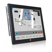
IEI Technology PPC-F17B User Manual (151 pages)
Industrial Panel PC with Intel Celeron Processor J1900, Touchscreen, Dual PCIe Mini, USB 3.0, HDMI SATA 6Gb/s, Dual PCIe GbE, iRIS-2400, IP 65 Compliant Front Panel and RoHS Compliant
Brand:
IEI Technology
| Category:
Touch Panel
| Size: 6 MB
Table of Contents
Table of Contents
7
Safety Instructions
3
Introduction
17
Overview
18
Figure 1-1: PPC-F12B/15B/17B/19B-Bti Series Panel PC
18
Model Variation
19
Features
19
Table 1-1: Model Variation
19
Front Panel
20
Rear Panel
20
Figure 1-2: Front View
20
Figure 1-3: PPC-F17B-Bti Rear View
20
Bottom Panel
21
Figure 1-4: PPC-F12B-Bti Bottom View
21
Figure 1-5: PPC-F15B/F17B-Bti Bottom View
21
Figure 1-6: PPC-F19B-Bti Bottom View
22
Dimensions
23
PPC-F12B-Bti Dimensions
23
Figure 1-7: PPC-F12B-Bti Dimensions (MM)
23
D IMENSIONS 1.7.1 PPC-F12B-Bti Dimensions
23
Figure 1-8: PPC-F15B-Bti Dimensions (MM)
24
PPC-F15B-Bti Dimensions
24
Figure 1-9: PPC-F17B-Bti Dimensions (MM)
25
PPC-F17B-Bti Dimensions
25
Figure 1-10: PPC-F19B-Bti Dimensions (MM)
26
PPC-F19B-Bti Dimensions
26
Specifications
27
Table 1-2: System Specifications
28
Unpacking
29
Unpacking
30
Packing List
31
Optional Items
32
Table 2-1: Packing List
32
Table 2-2: Optional Items
32
Installation
33
Anti-Static Precautions
34
Installation Precautions
34
Preinstalled Components
35
Installation and Configuration Steps
35
Removing the
36
So-DIMM Installation
36
Figure 3-1: PPC-F17B-Bti Back Cover Retention Screws
36
Figure 3-2: SO-DIMM Slot Location
37
Figure 3-3: SO-DIMM Heatspreader Installation
37
Hdd Installation
38
Figure 3-4: SO-DIMM Installation
38
Figure 3-5: PPC-F17B-Bti HDD Bracket Retention Screws
39
Figure 3-6: HDD Retention Screws
39
Msata Module Installation
40
Figure 3-7: PPC-F17B-Bti HDD Installation
40
Figure 3-8: Pcie Mini Card Slot Which Supports Msata
41
Figure 3-9: Removing the Retention Screws
41
Figure 3-10: Inserting the Pcie Mini Card into the Slot at an Angle
42
Figure 3-11: Securing the Pcie Mini Card
42
Iris-2400 Module Installation
43
Figure 3-12: Motherboard Retention Screws
43
Figure 3-13: Iris-2400 Module Slot Location
44
Figure 3-14: Iris-2400 Module Installation
44
Wireless LAN Module Installation (Optional)
45
Figure 3-15: Knockouts on Top Panel for Wireless Antennas
45
Figure 3-16: Pcie Mini Slot Location
46
Figure 3-17: Inserting the WLAN Module
46
Figure 3-18: Securing WLAN Module
47
Figure 3-19: Connecting RF Cables
47
Figure 3-20: Securing SMA Connector and External Antenna Installation
48
At/Atx Mode Selection
49
Figure 3-21: AT/ATX Mode Selection
49
Mounting the System
50
Wall Mounting
50
Figure 3-22: Wall-Mounting Bracket
51
Figure 3-23: Mount the Chassis
52
Figure 3-24: Secure the Chassis
53
Panel Mounting
53
Figure 3-25: PPC-F17B-Bti Mounting Bracket Installation
54
Figure 3-26: PPC-F12B-Bti Panel Cutout Dimensions
55
Figure 3-27: PPC-F15B-Bti Panel Cutout Dimensions
55
Figure 3-28: PPC-F17B-Bti Panel Cutout Dimensions
55
Figure 3-29: PPC-F19B-Bti Panel Cutout Dimensions
56
Figure 3-30: Tighten the Mounting Clamp Screws
57
Rack Mounting for F12B, F15B and F17B
58
Figure 3-31: PPC-F17B-Bti Mounting Bracket Installation
58
Figure 3-32: the Rack/Cabinet Bracket
58
Figure 3-33: Secure the Rack/Cabinet Bracket
59
Rack Mounting for F19B
60
Figure 3-34: Install into a Rack/Cabinet
60
Figure 3-35: PPC-F19B-Bti Mounting Bracket Installation
60
Figure 3-36: Slide through the Rack/Cabinet Bracket
61
Figure 3-36: PPC-F19B-Bti Side Bracket Installation
61
Figure 3-37: Secure the Rack/Cabinet Bracket
62
Rack and Cabinet Installation
57
Arm Mounting
63
Figure 3-38: Install into a Rack/Cabinet
63
Figure 3-39: Arm Mounting Retention Screw Holes
64
Figure 3-40: Arm Mounting (ARM-11-RS)
65
Stand Mounting
65
Figure 3-41: Stand Mounting Retention Screw Holes
66
Figure 3-42: Stand Mounting (Stand-Axx)
66
Serial Device Connection
67
Serial Ports (COM1, COM2)
67
Table 3-1: RS-232 Serial Port (COM1, COM2) Pinouts
67
Figure 3-43: Serial Port Locations
67
Table 3-2: RS-232/422/485 Serial Port (COM3) Pinouts
68
Figure 3-44: Power Input Connector Pinouts
68
Powering on the System
68
RS-232/422/485 Serial Port (COM3)
68
Figure 3-45: Power Connectors and Power Switch
69
Figure 3-46: Reset Button Location
69
Reset the System
69
Clear Cmos
70
Figure 3-47: Clear CMOS Button Location
70
Figure 3-48: BIOS Option-OS Selection
70
Os Installation
70
Driver Installation
71
Keypad AP
72
Ipmi Setup Procedure
72
Managed System Hardware Setup
72
Figure 3-49: Keypad AP
72
Figure 3-50: IEI Iman Web Address
73
Using the IEI Iman Web GUI
73
Figure 3-51: IEI Iman Web GUI
74
System Maintenance
75
System Maintenance Introduction
76
Motherboard Replacement
76
Bios Setup
77
Introduction
78
Starting Setup
78
Using Setup
78
BIOS Menu Bar
79
Getting Help
79
Unable to Reboot after Configuration Changes
79
Table 5-1: BIOS Navigation Keys
79
Main
80
Advanced
81
System Date [XX/XX/XX]
81
System Time [XX:XX:XX]
81
F81866 Super IO Configuration
82
Serial Port N Configuration
83
Change Settings [Auto]
83
Serial Port [Enabled]
83
Change Settings [Auto]
84
Serial Port [Enabled]
84
Change Settings [Auto]
85
Iwdd H/W Monitor
86
Serial Port [Enabled]
85
PC Health Status
86
RTC Wake Settings
87
Serial Port Console Redirection
88
Serial Port Mode [RS232]
86
Wake System with Fixed Time [Disabled]
88
Console Redirection Settings
89
Console Redirection [Disabled]
89
Bits Per Second [115200]
90
Terminal Type [ANSI]
90
Data Bits [8]
91
Parity [None]
91
Stop Bits [1]
91
Iei Feature
92
Auto Recovery Function [Disabled]
92
CPU Configuration
93
EIST [Enabled]
94
IDE Configuration
95
Intel Virtualization Technology [Enabled]
94
SATA Mode Selection [IDE Mode]
95
USB Configuration
96
Serial-ATA (SATA) [Enabled]
95
Legacy USB Support [Enabled]
96
USB Devices
96
Chipset
97
Intel IGD Configuration
98
North Bridge
98
DVMT Pre-Allocated [256M]
99
DVMT Total Gfx Mem [Max]
99
Primary Display [Auto]
99
Primary IGFX Boot Display [VBIOS Default]
99
South Bridge
100
Auto Power Button Status [Enable (AT)]
100
Audio Controller [Enabled]
101
Restore AC Power Loss [Last State]
101
XHCI Mode [Enabled]
101
PCI Express Configuration
102
Speed [Auto]
102
Administrator Password
103
Security
103
User Password
103
Boot
104
Bootup Numlock State [On]
104
OS Selection [Windows 8.X]
105
Quiet Boot [Enabled]
105
UEFI Boot [Disabled]
105
Launch PXE Oprom [Disabled]
106
Option ROM Messages [Force BIOS]
106
Save & Exit
106
Discard Changes and Reset
107
Restore Defaults
107
Restore User Defaults
107
Save as User Defaults
107
Save Changes and Reset
107
Server Mgmt
108
System Event Log
109
Erase SEL [No]
109
BMC Network Configuration
110
SEL Components [Enabled]
109
When SEL Is Full [Do Nothing]
110
Configuration Address Source [Unspecified]
111
Interface Connectors
112
Peripheral Interface Connectors
113
Figure 6-1: Main Board Layout Diagram (Front Side)
113
Internal Peripheral Connectors
114
Figure 6-2: Main Board Layout Diagram (Solder Side)
114
Table 6-1: Peripheral Interface Connectors
115
Audio Connector (AUDIO1)
116
Chassis Intrusion Connector (CHASSIS1)
116
Debug Port (DBG_PORT1)
116
Table 6-2: Audio Connector (AUDIO1) Pinouts
116
Table 6-3: Chassis Intrusion Connector (CHASSIS1) Pinouts
116
Table 6-4: Debug Port (DBG_PORT1) Pinouts
116
DIO Connector (DIO1)
117
EC Debug Port (CN2)
117
Table 6-5: DIO Connector (DIO1) Pinouts
117
Table 6-6: EC Debug Port (CN2) Pinouts
117
Fan Connector (CPU_FAN1)
118
Front Panel Connector (F_PANEL1)
118
I 2 C Connector (I2C1)
118
Table 6-7: Fan Connector (CPU_FAN1) Pinouts
118
Table 6-8: Front Panel Connector (F_PANEL1) Pinouts
118
Table 6-9: I 2 C Connector (I2C1) Pinouts
118
IPMI Active LED Connector (LEDCN1)
119
Keyboard and Mouse Connector (KB_MS1)
119
Keypad Connector (OSD1)
119
Table 6-10: IPMI Active LED Connector (LEDCN1) Pinouts
119
Table 6-11: Keyboard and Mouse Connector (KB_MS1) Pinouts
119
Table 6-12: Keypad Connector (OSD1) Pinouts
119
LAN Active LED Connectors (LAN_LED1)
120
LVDS Connector (LVDS1)
120
Table 6-13: LAN Active LED Connectors (LAN_LED1) Pinouts
120
Table 6-14: LVDS Connector (LVDS1) Pinouts
120
LVDS Backlight Connector (INVERTER1)
121
Pcie Mini (MINI_PCIE1) and Msata (M_SATA1) Card Slots
121
Table 6-15: LVDS Backlight Connector (INVERTER1) Pinouts
121
Power Button Connector (PWR_BTN1)
122
Power Source Connector (PWR1)
122
Reset Button Connector (RST_BTN2)
122
Table 6-16: Pcie Mini (MINI_PCIE1) and Msata (M_SATA1) Card Pinouts
122
Table 6-17: Power Button Connector (PWR_BTN1) Pinouts
122
Table 6-18: Power Source Connector (PWR1) Pinouts
122
Table 6-19: Reset Button Connector (RST_BTN2) Pinouts
122
Resistive Touchscreen Connector (TOUCH1)
123
Connector (COM4, COM5)
123
Table 6-20: Resistive Touchscreen Connector (TOUCH1) Pinouts
123
Table 6-21: RS-232 Connector (COM4, COM5) Pinouts
123
SATA 6Gb/S Connectors (SATA1, SATA2)
124
SATA Power Connectors (SATA_PWR1, SATA_PWR2)
124
Smbus Connector (SMB1)
124
Table 6-22: SATA 6Gb/S Connectors (SATA1, SATA2) Pinouts
124
Table 6-23: SATA Power Connectors (SATA_PWR1, SATA_PWR2) Pinouts
124
Table 6-24: Smbus Connector (SMB1) Pinouts
124
SPI Flash Connector (JSPI1)
125
SPI Flash (EC) Connector (JSPI2)
125
U3 Firmware Programming Connector (JP2)
125
Table 6-25: SPI Flash Connector (JSPI1) Pinouts
125
Table 6-26: SPI Flash (EC) Connector (JSPI2) Pinouts
125
USB 2.0 Connector (USB1)
126
External Interface Panel Connectors
126
Table 6-27: U3 Firmware Programming Connector (JP2) Pinouts
126
Table 6-28: USB 2.0 Connector (USB1) Pinouts
126
Table 6-29: Rear Panel Connectors
126
HDMI Connector (HDMI1)
127
Gbe Connectors (LAN1, LAN2)
127
Serial Ports (COM1, COM2)
127
Table 6-30: HDMI Connector (HDMI1) Pinouts
127
Table 6-31: RJ-45 Gbe Connector (LAN1, LAN2) Pinouts
127
Table 6-32: RS-232 Serial Port (COM1, COM2) Pinouts
127
RS-232/422/485 Serial Port (COM3)
128
USB 2.0 Connectors (USB_CON1)
128
USB 3.0 Connectors (USB3_CON1)
128
Table 6-33: RS-232/422/485 Serial Port (COM3) Pinouts
128
Table 6-34: USB 2.0 Connector (USB_CON1) Pinouts
128
VGA Connector (VGA1)
129
Preconfigured Jumpers
129
Table 6-35: USB 3.0 Connector (USB3_CON1) Pinouts
129
Table 6-36: VGA Connector (VGA1) Pinouts
129
Table 6-37: Preconfigured Jumpers
129
Backlight Voltage Selection Jumper (JP1)
130
LVDS Panel Resolution Selection Switch (SW1)
130
Table 6-38: Panel Voltage Selection Jumper (JP1) Settings
130
Table 6-39: LVDS Panel Resolution Selection
130
Panel Voltage Selection Jumper (JLCD_PWR1)
131
Table 6-40: Panel Voltage Selection Jumper (JLCD_PWR1) Settings
131
A Regulatory Compliance
132
B Bios Configuration Options
137
B.1 BIOS Configuration Options
138
B.1 Bios C Onfiguration O Ptions
138
Bios Configuration Options
138
C Safety Precautions
140
Safety Precautions
141
C.1 S Afety P Recautions
141
General Safety Precautions
141
Anti-Static Precautions
142
Product Disposal
143
Maintenance and Cleaning Precautions
144
C.2 M Aintenance and C Leaning P Recautions
144
Cleaning Tools
144
Maintenance and Cleaning
144
D Watchdog Timer
146
Example Program
148
E Hazardous Materials Disclosure
149
Advertisement
Advertisement
Related Products
IEI Technology PPC-F17B-BTi
IEI Technology PPC-F17D-ULT5-i5/4G/PC
IEI Technology PPC-F17D-ULT5-C/4G/PC
IEI Technology PPC-F17C-Q370-P/PC/25
IEI Technology PPC-F17C-Q370-i3/PC/25
IEI Technology PPC-F17C-Q370-i5/PC/25
IEI Technology PPC-F17C-Q370-i7/PC/25
IEI Technology PPC-F17B-BTi-J1/2G/R-R10
IEI Technology PPC-F17B-BTi-J1/2G/PC-R10
IEI Technology PPC-F17A-H81
IEI Technology Categories
Motherboard
Touch Panel
Computer Hardware
Single board computers
Desktop
More IEI Technology Manuals
Login
Sign In
OR
Sign in with Facebook
Sign in with Google
Upload manual
Upload from disk
Upload from URL