Sign In
Upload
Manuals
Brands
IEI Technology Manuals
Touch Panel
PPC-5190A-G41
IEI Technology PPC-5190A-G41 Manuals
Manuals and User Guides for IEI Technology PPC-5190A-G41. We have
1
IEI Technology PPC-5190A-G41 manual available for free PDF download: User Manual
IEI Technology PPC-5190A-G41 User Manual (152 pages)
PPC-51xxA-G41 series; WIDS-51xA-G41 
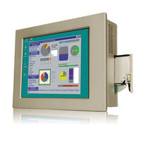
Industrial panel PC for LGA775 Intel Qaud Core CPU TFT LCD, dual gigabit ethernet, touchscreen, IP 65 front panel , RoHS compilian
Brand:
IEI Technology
| Category:
Touch Panel
| Size: 9 MB
Table of Contents
Table of Contents
4
1 Introduction
13
Figure 1-1: PPC-51Xxa-G41 Panel PC
14
Features
16
Figure 1-2: PPC-51Xxa-G41 Front View
17
General Overview
14
Model Variations
14
Applications
15
Table 1-1: PPC-51Xxa-G41 Model Variations
15
Table 1-2: WIDS-51Xa-G41 Model Variations
15
External Overview
16
Figure 1-3: WIDS-51Xa-G41 Front View
17
Front Panel
17
Figure 1-6: Bottom View
19
Figure 1-7: Left View
20
Figure 1-8: Right View
20
Figure 1-9: Internal Components
21
Internal Overview
21
Left Panel
20
Right Panel
20
Figure 1-4: Rear View
18
Figure 1-5: Top View
18
Rear Panel
18
Top Panel
18
Bottom Panel
19
2 Specifications
22
Introduction
23
System Specifications
23
PPC-51Xxa-G41 Specifications
23
Table 2-1: PPC-51Xxa-G41 Series System Specifications
25
WIDS-51Xa-G41Specifications
26
Dimensions
28
Table 2-2: WIDS-51Xa-G41 Series System Specifications
28
Figure 2-1: PPC-5150A-G41 Dimensions (Units in MM)
29
Figure 2-2: PPC-5170A-G41 Dimensions (Units in MM)
30
Figure 2-3: PPC-5190A-G41 Dimensions (Units in MM)
31
PPC-5190A-G41 Dimensions
31
Figure 2-4: WIDS-515A-G41 Dimensions (Units in MM)
32
WIDS-515A-G41 Dimensions
32
Figure 2-5: WIDS-517A-G41 Dimensions (Units in MM)
33
WIDS-517A-G41 Dimensions
33
Figure 2-6: DIMM Sockets
34
Graphics Support
34
Memory
34
Compactflash
35
Figure 2-7: Compactflash® Slot
35
Hard Drive
35
Storage
35
Figure 2-8: SATA Hard Drive Slot
36
Flat Screen
36
Front Panel
36
Touch Screen
36
ACE-4520C-RS Specifications
37
ACE-A622A-RS Specifications
37
Power Supply
37
Expansion Slots
38
Figure 2-9: Expansion Card Slot
38
Wireless LAN (WIDS Series Only)
38
PPC-5170A-G41 Dimensions
30
PPC-5150A-G41 Dimensions
29
Figure 2-10: Wireless LAN Module (Installed by Users)
39
Figure 2-11: Antenna
39
3 Unpacking
40
Anti-Static Precautions
41
Unpacking Precautions
41
Package Contents
42
Table 3-1: Package List Contents
43
4 Installation and Configuration
44
Installation Precautions
45
Preinstalled Components
45
Installation and Configuration Steps
46
Cover
47
Figure 4-1: Back Cover Retention Screws
47
Figure 4-2: CF Card Setup Jumper Location
50
Figure 4-3: COM1 to COM5 Pin 9 Setting Jumper Locations
51
Table 4-5: COM5 RS-232/422/485 Serial Port Select Jumper Settings
51
COM 5 RS-422 and RS-485 Pinouts
52
Figure 4-4: COM5 RS-232/422/485 Serial Port Select Jumper Location
52
Table 4-6: COM5 RS-422 Pinouts
52
Table 4-7: COM5 RS-485 Pinouts
52
Drive Installation
53
Hard Drive Installation
53
Table 4-4: COM1 to COM5 Pin 9 Setting Jumper Settings
50
COM5 RS-232/422/485 Serial Port Select Jumper
51
Remove the
47
Jumper Settings
48
Access the Jumpers
48
Table 4-1: Jumpers
48
CF Card Setup
49
Preconfigured Jumpers
49
Table 4-2: Preconfigured Jumpers
49
Table 4-3: CF Card Setup Jumper Settings
49
COM1 to COM5 Pin 9 Select
50
Figure 4-5: HDD Retention Screws
53
Figure 4-7: HDD Retention Screws
54
Figure 4-6: HDD SATA Connector
54
Figure 4-8: HDD Retention Screws
55
Figure 4-9: Compactflash® Cover Plate
55
CD Drive Installation
56
Compactflash Installation
55
Figure 4-11: Compactflash® Cover Plate
56
Figure 4-10: Compactflash® Slot
56
Figure 4-13: CD Drive Retention Screws
57
Figure 4-14: Optical Drive Blank Plate Assembly
58
Figure 4-15: Optical Drive Screws
59
Figure 4-16: Optical Drive SATA Cable
60
Figure 4-17: Optical Drive Bracket Screws
60
Figure 4-19: Expansion Slot Retention Screw
62
Figure 4-20: Install PCI Card
62
Figure 4-22: Expansion Slot Retention Screw
64
Figure 4-23: Install Pcie Card
64
Activating the Front USB Connectors (WIDS Series Only)
65
At/Atx Mode Selection
65
Figure 4-24: AT/ATX Power Switch Selection
65
Figure 4-25: Access the Front USB Connectors
66
Figure 4-26: USB Switch
66
Figure 4-27: Green LED
67
Mounting the System
67
Wall Mounting
67
Figure 4-28: Wall-Mounting Bracket
68
Figure 4-29: Mount the Chassis
69
Panel/ Mounting
70
Figure 4-12: CD Drive Adapter Installation
57
Figure 4-21: Secure the Pcie Riser Card
63
Pcie Expansion Card Installation (Optional)
63
Figure 4-30: Secure the Chassis
70
Figure 4-32: PPC-5170A-G41 Panel Cutout Dimensions
71
Figure 4-31: PPC-5150A-G41 Panel Cutout Dimensions
71
Figure 4-34: WIDS-515A-G41 Panel Cutout Dimensions
72
Figure 4-33: PPC-5190A-G41 Panel Cutout Dimensions
72
Figure 4-35: WIDS-517A-G41 Panel Cutout Dimensions
73
Figure 4-36: Panel Mounting Clamp Positions
74
Figure 4-37: Tighten the Panel Mounting Clamp Screws
74
Arm Mounting
75
Rack and Cabinet Installation
75
Figure 4-18: Secure the PCI Riser Card
61
PCI Expansion Card Installation (Optional)
61
Figure 4-38: Arm Mount Retention Screw Holes
76
5 Bios Setup
77
Introduction
79
Starting Setup
79
Using Setup
79
Getting Help
80
Unable to Reboot after Configuration Changes
80
BIOS Menu Bar
80
Table 5-1: BIOS Navigation Keys
80
Main
81
BIOS Menu 1: Main
81
Advanced
82
CPU Configuration
83
BIOS Menu 2: Advanced
83
BIOS Menu 3: CPU Configuration
83
IDE Configuration
84
BIOS Menu 4: IDE Configuration
84
BIOS Menu 5: IDE Master and IDE Slave Configuration
86
IDE Master, IDE Slave
86
Super IO Configuration
89
BIOS Menu 6: Super IO Configuration
90
Hardware Health Configuration
95
BIOS Menu 7: Hardware Health Configuration
95
Power Configuration
98
BIOS Menu 8: Power Configuration
98
ACPI Settings
99
APM Configuration
99
BIOS Menu 9: ACPI Settings
99
BIOS Menu 10: APM Configuration
100
Remote Access Configuration
102
BIOS Menu 11: Remote Access Configuration
102
USB Configuration
105
BIOS Menu 12: USB Configuration
105
Pci/Pnp
107
BIOS Menu 13: Pci/Pnp Configuration
107
Boot
109
BIOS Menu 14: Boot
109
BIOS Menu 15: Boot Settings Configuration
110
Boot Settings Configuration
110
Security
112
BIOS Menu 16: Security
112
Chipset
113
BIOS Menu 17: Chipset
113
North Bridge Configuration
114
BIOS Menu 18:North Bridge Chipset Configuration
114
Video Function Configuration
115
BIOS Menu 19: South Bridge Chipset Configuration
116
BIOS Menu 20: South Bridge Chipset Configuration
116
South Bridge Configuration
116
Exit
117
BIOS Menu 21: Exit
117
6 System Maintenance
119
Back Cover Removal
120
Motherboard Replacement
120
System Maintenance Introduction
120
DIMM Replacement
121
Elevated Platform Removal
122
Figure 6-2: Top Panel Elevated Platform Screws
122
Figure 6-5: Internal Elevated Platform Screws
124
Figure 6-7: PSU Bottom Panel Retention Screws
125
Figure 6-6: PSU Power Cables
125
Install the New PSU
126
System Cooling Fan Replacement
127
Figure 6-9: System Cooling Fans Motherboard Connector
127
Remove the Old System Cooling Fans
127
Install the New System Cooling Fans
128
Figure 6-1: DIMM Socket Clip Locations
122
Figure 6-4: Bottom Panel Elevated Platform Screws
123
Figure 6-3: Side Panel Elevated Platform Screws
123
Psu Module Replacement
124
Remove the Old PSU
124
ABIOS Options
129
B Terminology
133
C Digital I/O Interface
137
Introduction
138
Dio Connector Pinouts
138
Assembly Language Samples
139
Enable the DIO Input Function
139
Enable the DIO Output Function
139
D Watchdog Timer
140
E Address Mapping
143
Direct Memory Access (Dma)
144
A Ccess (Dma)
144
Input/Output (IO)
145
Interrupt Request (Irq)
147
R Equest (Irq)
147
Memory
148
F Hazardous Materials Disclosure
149
Hazardous Materials Disclosure Table for IPB Products Certified as Rohs Compliant under 2002/95/EC Without Mercury
150
Advertisement
Advertisement
Related Products
IEI Technology PPC-5152-D525-E
IEI Technology PPC-5152-D525
IEI Technology PPC-5170A-G41
IEI Technology PPC-5150A-G41
IEI Technology PPC-5050A
IEI Technology PPC-5020
IEI Technology PPC-F17B-BTi
IEI Technology PPC-3708A-N270
IEI Technology PPC-FW22C-Q370-i7/PC/25
IEI Technology PPC2-C104-ADLP-i7/8G
IEI Technology Categories
Motherboard
Touch Panel
Computer Hardware
Single board computers
Desktop
More IEI Technology Manuals
Login
Sign In
OR
Sign in with Facebook
Sign in with Google
Upload manual
Upload from disk
Upload from URL