Sign In
Upload
Manuals
Brands
IEI Technology Manuals
Touch Panel
PPC-5152-D525
IEI Technology PPC-5152-D525 Manuals
Manuals and User Guides for IEI Technology PPC-5152-D525. We have
1
IEI Technology PPC-5152-D525 manual available for free PDF download: User Manual
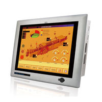
IEI Technology PPC-5152-D525 User Manual (185 pages)
Flat-bezel Panel PC with Touch Screen and Intel AtomTM CPU, USB 3.0, Dual Combo (SFP Fiber/RJ-45) Gigabit LAN, Audio, RS-232/422/485, RoHS Compliant, IP 65 Protection
Brand:
IEI Technology
| Category:
Touch Panel
| Size: 11 MB
Table of Contents
Table of Contents
5
1 Introduction
15
Overview
16
Figure 1-1: PPC-5152-D525 Panel PC
16
Model Variations
17
Features
17
Table 1-1: Model Variations
17
External Overview
18
Front Panel
18
Figure 1-2: Front View
19
Figure 1-3: LED Indicators
19
LED Indicators
19
Bottom Panel
20
Table 1-2: LED Indicators
20
Figure 1-4: Bottom View
21
Figure 1-5: Side View
22
Side Panels
22
Figure 1-6: Top View
23
Figure 1-7: Rear View
23
Rear Panel
23
Top Panel
23
Backplane Options
24
Figure 1-8: Backplane Option 1 (HPE-2S1)
24
Figure 1-9: Backplane Option 2 (HPE-2S2)
24
Dimensions
25
Figure 1-10: PPC-5152-D525 Dimensions (MM)
25
Specifications
26
Table 1-3: System Specifications
28
2 Unpacking
29
Unpacking
30
Packing List
31
3 Installation
33
Anti-Static Precautions
34
Installation Precautions
34
Preinstalled Components
35
Compactflash® Installation
35
Figure 3-1: Compactflash® Cover Plate
35
USB Devices Installation (Internal)
36
Figure 3-2: Compactflash® Slot
36
Figure 3-3: Remove the Internal USB Port Access Panel
37
Figure 3-4: Internal USB Port Location
37
SFP Optical Module Installation (Optional)
38
Figure 3-5: SFP Optical Module
38
Figure 3-6: SFP Module Installation
38
Hdd Installation
39
Figure 3-7: Rear Panel Retention Screws
39
Figure 3-8: HDD Bracket Retention Screws
40
Figure 3-9: HDD Installation
40
Figure 3-10: HDD Bracket Installation
41
Pci Expansion Card Installation
42
Figure 3-11: Expansion Slot Retention Screw
43
Figure 3-12: Install PCI Card
43
Pcie Expansion Card Installation (Optional)
44
Figure 3-13: Expansion Slot Retention Screw
45
Figure 3-14: Install Pcie Card
45
Mounting the System
46
Arm Mounting
46
Figure 3-15: VESA Compliant Arm
46
Figure 3-16: Arm Mounting Retention Screw Holes
47
Figure 3-17: Suggested Panel Cut out Size for PPC-5152-D525 (Unit: MM)
48
Panel Mounting
48
Figure 3-18: Panel Mounting Clamp Slots (Side View)
49
Figure 3-19: Tighten the Panel Mounting Clamp Screws
50
Rack/Cabinet Mounting
50
Figure 3-20: the Rack/Cabinet Bracket
51
Figure 3-21: Secure the Rack/Cabinet Bracket
51
Figure 3-22: Install into a Rack/Cabinet
52
Figure 3-23: VESA Compliant Stand
52
Stand Mounting
52
Figure 3-24: Stand Mounting Retention Screw Holes
53
Wall Mounting
53
Figure 3-25: Wall-Mounting Bracket
54
Figure 3-26: Chassis Support Screws
55
Bottom Panel Connectors
56
Audio Connectors
56
Figure 3-27: Secure the Panel PC
56
Figure 3-28: RJ-45 Ethernet Connector
57
LAN Connector
57
Table 3-1: LAN Pinouts
57
Table 3-2: RJ-45 Ethernet Connector Leds
57
Figure 3-29: LAN Connection
58
Power Input, 2-Pin Terminal Block
58
Figure 3-30: 2-Pin Terminal Block Pinouts
59
Figure 3-31: Power Input Terminal Block Installation
59
Power Input, DIN Connector
59
Figure 3-32: RS-232 Serial Port
60
Serial Port (COM1, COM2)
60
Table 3-3: RS-232 Serial Port Pinouts
60
Figure 3-33: RS-232/422/485 Serial Port
61
RS-232/422/485 Serial Port (COM3)
61
Table 3-4: RS-232/422/485 Serial Port Pinouts
61
COM3 Mode Select Switch
62
Figure 3-34: Serial Device Connector
62
Table 3-5: COM3 RS-232/422/485 Serial Port Select Settings
62
Figure 3-35: COM3 RS-232/422/485 Serial Port Select Switch Location
63
Figure 3-36: RJ-45 RS-422/485 Serial Port
63
RS-422/485 Serial Port (COM4, COM5)
63
Figure 3-37: RJ-45 RS-422/485 Serial Device Connection
64
Table 3-6: RJ-45 RS-422/485 Serial Port Pinouts
64
Figure 3-38: RS-422/485 Serial Port (DB-9)
65
SFP Fiber Connectors
65
Table 3-7: RS-422/485 Serial Port Pinouts
65
USB 2.0 Connectors
65
Table 3-8: USB 2.0 Port Pinouts
66
Table 3-9: USB 3.0 Port Pinouts
66
USB 3.0 Connectors
66
Figure 3-39: USB Device Connection
67
VGA Connector
67
Figure 3-40: VGA Connector
68
Table 3-10: VGA Connector Pinouts
68
Power-Up the System
69
AT/ATX Power Mode Selection
69
Figure 3-41: VGA Connector
69
Figure 3-42: AT/ATX Power Mode Switch
69
Powering On/Off in ATX Power Mode
70
Remote Control
70
Figure 3-43: Power Button
70
Figure 3-44: Remote Control
70
4 System Maintenance
71
System Maintenance Introduction
72
Anti-Static Precautions
72
Turn off the Power
73
Opening the System
73
Replacing Components
74
Figure 4-1: Back Cover Retention Screws
74
Memory Module Replacement
74
Figure 4-2: DDR SO-DIMM Module Installation
75
WLAN Card Replacement
75
Figure4-3: Removing the Antennas
76
Figure4-4: Releasing the WLAN Card
76
Figure4-5: Removing the WLAN Card
77
Figure4-6: Attaching the Antennas
78
5 Ami Bios Setup
79
Introduction
80
Starting Setup
80
Using Setup
80
BIOS Menu Bar
81
Getting Help
81
Table 5-1: BIOS Navigation Keys
81
Main
82
BIOS Information
82
System Date [XX/XX/XX]
82
Advanced
83
ACPI Settings
83
System Time [XX:XX:XX]
83
ACPI Sleep State [S1 (CPU Stop Clock)]
84
Power Saving Function [Disabled]
84
CPU Configuration
85
IDE Configuration
86
Hyper Threading Function [Enabled]
86
ATA/IDE Configurations [Enhanced]
86
USB Configuration
87
Configure SATA as [IDE]
87
USB Devices
88
Legacy USB Support [Enabled]
88
USB3.0 Support [Enabled]
88
Serial Port N Configuration
89
Super IO Configuration
89
Serial Port [Enabled]
89
Change Settings [Auto]
89
Serial Port [Enabled]
90
Change Settings [Auto]
91
Serial Port 3 Mode [RS232]
92
Serial Port [Enabled]
93
Change Settings [Auto]
93
Serial Port 4 Mode [RS422/485]
93
Change Settings [Auto]
94
Serial Port 5 Mode [RS422/485]
94
Serial Port [Enabled]
94
H/W Monitor
95
Serial Port Console Redirection
96
PC Health Status
96
Console Redirection Settings
97
Console Redirection [Disabled]
97
Terminal Type [ANSI]
98
Bits Per Second [115200]
98
IEI Feature
99
Chipset
99
Host Bridge Configuration
100
South Bridge Configuration
101
Intel IGD SWSCI Opregion
103
Boot
105
Save & Exit
106
6 Software Drivers
108
Available Software Drivers
109
Starting the Driver Program
109
Chipset Driver Installation
109
Figure 6-1: Chipset Driver Screen
110
Figure 6-2: Chipset Driver Welcome Screen
111
Figure 6-3: Chipset Driver License Agreement
111
Figure 6-4: Chipset Driver Read Me File
112
Figure 6-5: Chipset Driver Setup Operations
112
Graphics Driver Installation
113
Figure 6-6: Chipset Driver Installation Finish Screen
113
Figure 6-7: Graphics Driver Read Me File
114
Figure 6-8: Graphics Driver Setup Files Extracted
114
Figure 6-9: Graphics Driver Welcome Screen
115
Figure 6-10: Graphics Driver License Agreement
115
Figure 6-11: Graphics Driver Read Me File
116
Figure 6-12: Graphics Driver Setup Operations
116
Lan Driver Installation
117
Figure 6-13: Graphics Driver Installation Finish Screen
117
Figure 6-14: LAN Driver Welcome Screen
118
Figure 6-15: LAN Driver Welcome Screen
118
Figure 6-16: LAN Driver Installation
119
Figure 6-17: LAN Driver Installation Complete
119
Audio Driver Installation
120
Figure 6-18: Audio Driver Welcome Screen
120
Figure 6-19: Audio Driver Installation
121
Figure 6-20: AC'97 Driver Installation Complete
121
Touch Screen Driver Installation
122
Figure 6-21: Touch Screen Driver Welcome Screen
122
Figure 6-22: Touch Screen Driver License Agreement
123
Figure 6-23: Touch Screen Driver Choose Install Location
123
Figure 6-24: Touch Screen Driver Installation Screen
124
Figure 6-25: Touch Screen Driver Update Complete
124
Calibrating the Touch Screen
125
Figure 6-26: Penmount Monitor Icon
125
Figure 6-27: Penmount Monitor Popup Menu
125
Figure 6-28: Configuration Screen
126
Figure 6-29: Calibration Initiation Screen
126
Usb 3.0 Driver Installation
127
Figure 6-30: Calibration Screen
127
Figure 6-31: USB 3.0 Driver Welcome Screen
128
Figure 6-32: USB 3.0 Driver License Agreement
128
Figure 6-33: USB 3.0 Driver Installation Screen
129
Figure 6-34: USB 3.0 Driver Update Complete
129
A Bios Configuration Options
130
A.1 BIOS Configuration Options
131
A.1 Bios C Onfiguration O Ptions
131
Bios Configuration Options
131
B One Key Recovery
133
One Key Recovery Introduction
134
Figure B-1: IEI One Key Recovery Tool Menu
134
B.1 O Ne K Ey R Ecovery I Ntroduction
134
System Requirement
135
Supported Operating System
136
Setup Procedure for Windows
137
B.2 S Etup P Rocedure for W Indows
137
Create Partitions
138
Hardware and BIOS Setup
138
Figure B-2: Launching the Recovery Tool
139
Figure B-3: Recovery Tool Setup Menu
139
Figure B-4: Command Prompt
140
Figure B-5: Partition Creation Commands
141
Install Operating System, Drivers and Applications
142
Building the Recovery Partition
143
Figure B-6: Launching the Recovery Tool
143
Figure B-7: Manual Recovery Environment for Windows
143
Figure B-8: Building the Recovery Partition
144
Figure B-9: Press any Key to Continue
144
Create Factory Default Image
145
Figure B-10: Press F3 to Boot into Recovery Mode
145
Figure B-11: Recovery Tool Menu
145
Figure B-12: about Symantec Ghost Window
146
Figure B-13: Symantec Ghost Path
146
Figure B-14: Select a Local Source Drive
147
Figure B-15: Select a Source Partition from Basic Drive
147
Figure B-16: File Name to Copy Image to
148
Figure B-17: Compress Image
148
Figure B-18: Image Creation Confirmation
149
Figure B-19: Image Creation Complete
149
Figure B-20: Image Creation Complete
149
Auto Recovery Setup Procedure
150
Figure B-21: Press any Key to Continue
150
B.3 a Uto R Ecovery S Etup P Rocedure
150
Figure B-22: Auto Recovery Utility
151
Figure B-23: Launching the Recovery Tool
151
Figure B-24: Auto Recovery Environment for Windows
151
Figure B-25: Building the Auto Recovery Partition
152
Figure B-26: Factory Default Image Confirmation
152
Figure B-27: Image Creation Complete
153
Figure B-28: Press any Key to Continue
153
Setup Procedure for Linux
154
Auto Recovery Function [Disabled]
154
B.4 S Etup P Rocedure for L Inux
154
Figure B-29: Partitions for Linux
155
Figure B-30: Manual Recovery Environment for Linux
156
Figure B-31: Access Menu.lst in Linux (Text Mode)
157
Figure B-32: Recovery Tool Menu
157
Recovery Tool Functions
158
Figure B-33: Recovery Tool Main Menu
158
B.5 R Ecovery T Ool F Unctions
158
Factory Restore
159
Figure B-34: Restore Factory Default
159
Backup System
160
Figure B-35: Recovery Complete Window
160
Figure B-36: Backup System
160
Figure B-37: System Backup Complete Window
161
Figure B-38: Restore Backup
161
Restore Your Last Backup
161
Figure B-39: Restore System Backup Complete Window
162
Figure B-40: Symantec Ghost Window
162
Manual
162
Restore Systems from a Linux Server through Lan
163
B.6 R Estore S Ystems from a L Inux S Erver through Lan
163
Configure DHCP Server Settings
164
Configure TFTP Settings
165
Configure One Key Recovery Server Settings
166
Create Shared Directory
167
Start the DHCP, TFTP and HTTP
167
Setup a Client System for Auto Recovery
168
Other Information
171
B.7 O Ther I Nformation
171
Using AHCI Mode or Ali M5283 / VIA VT6421A Controller
171
System Memory Requirement
173
C Safety Precautions
174
Safety Precautions
175
C.1 S Afety P Recautions
175
General Safety Precautions
175
Anti-Static Precautions
176
Product Disposal
176
Maintenance and Cleaning Precautions
177
C.2 M Aintenance and C Leaning P Recautions
177
Maintenance and Cleaning
177
Cleaning Tools
178
D Watchdog Timer
179
Example Program
181
E Hazardous Materials Disclosure
182
Hazardous Material Disclosure Table for IPB Products Certified as Rohs Compliant under 2002/95/EC Without Mercury
183
Advertisement
Advertisement
Related Products
IEI Technology PPC-5152-D525-E
IEI Technology PPC-5170A-G41
IEI Technology PPC-5150A-G41
IEI Technology PPC-5190A-G41
IEI Technology PPC-5050A
IEI Technology PPC-5020
IEI Technology PPC-F12B-BT
IEI Technology PPC2-CW133-ADLP-i3/8G
IEI Technology PPC2-CW185-ADLP-i3/8G
IEI Technology PPC2-CW215-ADLP-i3/8G
IEI Technology Categories
Motherboard
Touch Panel
Computer Hardware
Single board computers
Desktop
More IEI Technology Manuals
Login
Sign In
OR
Sign in with Facebook
Sign in with Google
Upload manual
Upload from disk
Upload from URL