Sign In
Upload
Manuals
Brands
IEI Technology Manuals
Touch Panel
PPC-3712B-N270
IEI Technology PPC-3712B-N270 Manuals
Manuals and User Guides for IEI Technology PPC-3712B-N270. We have
1
IEI Technology PPC-3712B-N270 manual available for free PDF download: User Manual
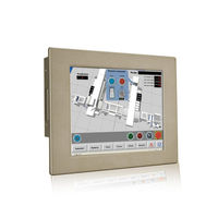
IEI Technology PPC-3712B-N270 User Manual (155 pages)
PPC-37xx-N270 series. Panel PC with touch screen and Intel Atom CPU gigabit ethernet, two USB, audio, RS-232/422/485, sata RoHS compliant, IP 65 protection
Brand:
IEI Technology
| Category:
Touch Panel
| Size: 5 MB
Table of Contents
Table of Contents
4
1 Introduction
15
Overview
16
Figure 1-1: PPC-37Xx-N270 Panel PC
16
Features
17
Model Variations
17
Table 1-1: Model Variations
17
Applications
18
External Overview
18
Figure 1-2: Front View
18
Front Panel
18
Bottom Panel
19
Figure 1-3: PPC-3712A/B-N270 Wall-Mounting Bracket Retention Screw Holes
19
Rear Panel
19
Figure 1-4: PPC-3708A-N270 Bottom View
20
Figure 1-5: PPC-3710A-N270 Bottom View
20
Figure 1-6: PPC-3712A/B-N270 Bottom View
20
Figure 1-7: PPC-3712B-N270 Bottom View
21
Figure 1-8: PPC-3712A/B-N270 Left View
21
Frame
21
Side Panel
21
Specifications
22
Figure 1-9: PPC-3712 Frame Rear View
22
Table 1-2: System Specifications
23
2 Detailed Specifications
24
Dimensions
25
Figure 2-1: PPC-3708A-N270 Dimensions (Units in MM)
25
PPC-3708A-N270 Dimensions
25
Figure 2-2: PPC-3710A-N270 Dimensions (Units in MM)
26
PPC-3710A-N270 Dimensions
26
Figure 2-3: PPC-3712A/B-N270 Dimensions (Units in MM)
27
PPC-3712A/B-N270 Dimensions
27
Figure 2-4: PPC-3712B-N270 Dimensions (Units in MM)
28
PPC-3712B-N270 Dimensions
28
Intel® Atom™ Processor
29
Motherboard Components
29
Installed Memory
29
Memory Support
29
Additional Memory
30
Figure 2-5: PPC-3708A SATA Hard Disk Drive Bay
30
Figure 2-6: PPC-3708A Compactflash® Slot
30
Storage Capacity
30
External Peripheral Interface Connectors
31
Figure 2-7: PPC-3708A COM Ports
31
Serial Port Connectors
31
External USB Connectors
32
Figure 2-8: PPC-3708A RJ-45 Ethernet Connectors
32
LAN Connectivity
32
Figure 2-10: PPC-3708A PS/2 Connector
33
Figure 2-9: PPC-3708A External USB Ports
33
Keyboard and Mouse Connectivity
33
N270 Front Side
34
Monitor
34
Touch-Screen Module
34
Graphics
34
Figure 2-11: LCD Screen
34
Intel ® 945GSE Integrated Graphics Engine
34
Dual-Display
35
Audio
35
Figure 2-12: PPC-3708A VGA Connector
35
Figure 2-13: PPC-3708A Audio Jack
35
System Power
36
Figure 2-14: Power Connector
36
PPC-3712B-N270 Power
36
PPC-37Xxa-N270 Series Power
36
Table 2-1: PPC-3712B-N270 Power Supply Specifications
37
3 Unpacking
38
Unpacking
39
Packing List
40
4 Installation
42
Anti-Static Precautions
43
Installation Precautions
43
Preinstalled Components
44
Installation and Configuration Steps
44
Remove the
45
Figure 4-1: PPC-3708 Back Cover Retention Screws
45
Figure 4-2: PPC-3710 Back Cover Retention Screws
45
PPC-3708 Back Cover Removal
45
PPC-3710 Back Cover Removal
45
PPC-3712 Back Cover Removal
46
Jumper Settings
46
Compactflash® Card Installation
46
Figure 4-3: PPC-3712 Back Cover Retention Screws
46
Hdd Installation
47
Figure 4-4: CF Card Installation
47
PPC-3708 HDD Installation
47
Figure 4-5: PPC-3708 HDD Bracket Retention Screws (Tope Panel)
48
Figure 4-6: PPC-3708 HDD Bracket Retention Screws (Inside)
48
Figure 4-7: PPC-3708 HDD Retention Screws
48
Figure 4-8: PPC-3710 HDD Bracket Retention Screws
49
PPC-3710 HDD Installation
49
Figure 4-9: PPC-3710 HDD Retention Screws
50
PPC-3712 HDD Installation
50
Figure 4-10: PPC-3712 HDD Bracket Retention Screws
51
Figure 4-11: PPC-3712 HDD Retention Screws
51
CD Drive Installation (PPC-3712A/B-N270 Only)
52
Figure 4-12: CD Drive Adapter Installation
52
Figure 4-13: PPC-3712 CD Drive Bracket
53
Figure 4-14: CD Drive Cover Bracket Retention Screws
53
Jumper Settings
54
Figure 4-15: Jumper Locations
54
Access the Jumpers
55
Preconfigured Jumpers
55
Table 4-1: Jumpers
55
Table 4-2: Preconfigured Jumpers
55
AT Power Select Jumper Settings
56
Table 4-3: at Power Select Jumper Settings
56
CF Card Setup
57
Figure 4-16: at Power Select Jumper Location
57
Table 4-4: CF Card Setup Jumper Settings
57
Clear CMOS Jumper
58
Figure 4-17: CF Card Setup Jumper Location
58
COM 2 Function Select Jumper
59
Figure 4-18: Clear CMOS Jumper
59
Table 4-5: Clear CMOS Jumper Settings
59
COM2 RS-422 and RS-485 Pinouts
60
Figure 4-19: COM 2 Function Select Jumper Location
60
Table 4-6: COM 2 Function Select Jumper Settings
60
Table 4-7: RS-422 Pinouts
60
Table 4-8: RS-485 Pinouts
60
Mounting the System
61
Wall Mounting
61
Figure 4-20: Wall-Mounting Bracket
62
Figure 4-21: Mount the Chassis
63
Figure 4-22: Secure the Chassis
64
Panel Mounting
64
PPC-3708A-N270 and PPC-3710A-N270
64
Figure 4-23: Suggested Panel Cut out Size for PPC-3708A-N270
65
Figure 4-24: Suggested Panel Cut out Size for PPC-3710A-N270
65
Figure 4-25: Tighten the Panel Mounting Clamp Screws
66
Figure 4-26: PPC-3712 Panel Mounting Kit
66
Ppc-3712A/B-N270
66
Figure 4-27: Suggested Panel Cut out Size for PPC-3712A/B-N270
67
Arm Mounting
68
Figure 4-28: Tighten the Panel Mounting Clamp Screws
68
Cabinet and Rack Installation
69
Figure 4-29: Arm Mounting Retention Screw Holes
69
Ppc-3708A-N270
69
Figure 4-30: the Rack/Cabinet Bracket
70
Figure 4-31: Secure the PPC-3708A-N270 Rack/Cabinet Bracket
70
Figure 4-32: Install into a Rack/Cabinet
71
PPC-3710A-N270 and PPC-3712A/B-N270
71
Rear Panel Connectors
72
Figure 4-33: Secure the Rack/Cabinet Bracket
72
Keyboard and Mouse Connection
72
LAN Connection
72
Figure 4-34: LAN Connection
73
Serial Device Connection
73
Figure 4-35: Serial Device Connector
74
USB Device Connection
74
Figure 4-36: USB Device Connection
75
VGA Monitor Connection
75
System Maintenance
76
Figure 4-37: VGA Connector
76
5 Bios Screens
77
Introduction
78
Starting Setup
78
Using Setup
78
BIOS Menu Bar
79
Getting Help
79
Table 5-1: BIOS Navigation Keys
79
Unable to Reboot after Configuration Changes
79
Main
80
System Overview
80
Advanced
81
System Time [XX:XX:XX]
81
System Date [XX/XX/XX]
81
CPU Configuration
82
IDE Configuration
83
ATA/IDE Configurations [Compatible]
84
Legacy IDE Channels [PATA Pri, SATA Sec]
84
IDE Master, IDE Slave
85
IDE Master and IDE Slave
85
Auto-Detected Drive Parameters
86
Type [Auto]
87
Zip
87
Lba/Large Mode [Auto]
87
Block (Multi Sector Transfer) [Auto]
88
PIO Mode [Auto]
88
DMA Mode [Auto]
89
Super IO Configuration
90
Auto]
90
32Bit Data Transfer [Enabled]
90
Parallel Port Address [Disabled]
91
Parallel Port Mode [Normal]
91
Parallel Port IRQ [IRQ7]
92
Serial Port1 Address [3F8/IRQ4]
92
Serial Port1 Mode [Normal]
92
Serial Port2 Address [2F8/IRQ3]
93
Serial Port2 Mode [Normal]
93
Serial Port3 Address [3E8]
93
Hardware Health Configuration
94
Serial Port3 IRQ [11]
94
Serial Port4 Address [2E8]
94
Serial Port4 IRQ [10]
94
CPU FAN Mode Setting [Full on Mode]
95
CPU Temp. Limit of off [000]
96
CPU Temp. Limit of Start [020]
96
CPU Fan Start PWM [070]
97
Slope PWM [0.5 PWM]
97
Power Configuration
98
ACPI Configuration
99
Suspend Mode [S1(POS)]
99
APM Configuration
100
Restore on AC Power Loss [Last State]
100
Power Button Mode [On/Off]
100
Resume on Keyboard/Mouse [Disabled]
101
Resume on Ring [Disabled]
101
Resume on PCI-Express WAKE# [Enabled]
101
Remote Configuration
102
Resume on RTC Alarm [Disabled]
102
RTC Alarm Date (Days)
102
System Time
102
Remote Access [Disabled]
103
Serial Port Number
103
Serial Port Mode
103
Flow Control
103
Redirection after BIOS POST
103
Terminal Type
103
VT-UTF8 Combo Key Support
104
Serial Port Number [COM1]
104
Base Address, IRQ [2F8H,3]
104
Serial Port Mode [115200 8,N,1]
104
Flow Control [None]
105
Redirection after BIOS POST [Always]
105
Terminal Type [ANSI]
105
VT-UTF8 Combo Key Support [Disabled]
105
USB Configuration
106
Sredir Memory Display Delay [Disabled]
106
USB Functions [Enabled]
107
USB 2.0 Controller [Enabled]
107
USB2.0 Controller Mode [Hispeed]
107
Pci/Pnp
108
Legacy USB Support [Enabled]
108
IRQ# [Available]
109
DMA Channel# [Available]
110
Reserved Memory Size [Disabled]
110
Boot
111
Boot Settings Configuration
111
Quick Boot [Enabled]
112
Quiet Boot [Disabled]
112
Addon ROM Display Mode [Force BIOS]
113
Bootup Num-Lock [Off]
113
Boot from LAN Support [Disabled]
113
Boot Device Priority
114
Security
115
Change Supervisor Password
115
Change User Password
115
Chipset
116
North Bridge Chipset Configuration
117
Memory Hole [Disabled]
117
Internal Graphics Mode Select [Enable, 8MB]
118
DVMT Mode Select [DVMT Mode]
118
DVMT/FIXED Memory
118
Boot Display Device [CRT]
119
LVDS Panel Type
119
LCD Brightness Control
119
TV Standard
119
Southbridge Configuration
120
Audio Controller [All Disabled]
120
Exit
121
Save Changes and Exit
121
Discard Changes and Exit
122
Discard Changes
122
Load Optimal Defaults
122
Load Failsafe Defaults
122
6 Driver Installation
123
Available Software Drivers
124
Driver CD Auto-Run
124
Chipset Driver Installation
125
Figure 6-1: Available Drivers
125
Figure 6-2: Chipset Driver Installation Program
125
Figure 6-3: Chipset Driver Installation Welcome Screen
126
Figure 6-4: Chipset Driver Installation License Agreement
126
Intel ® Graphics Media Accelerator Driver
127
Figure 6-5: Chipset Driver Readme File Information
127
Figure 6-6: Chipset Driver Installation Complete
127
Figure 6-7: Select the Operating System
128
Figure 6-8: VGA Driver
128
Figure 6-9: GMA Driver Readme File
129
Figure 6-10: GMA Driver File Extraction
129
Figure 6-11: GMA Driver Installation Welcome Screen
130
Figure 6-12: GMA Driver License Agreement
130
Broadcom LAN Driver (for Gbe LAN) Installation
131
Figure 6-13: GMA Driver Installing Notice
131
Figure 6-14: GMA Driver Installation Complete
131
Figure 6-15: Access Windows Control Panel
132
Figure 6-16: Double Click the System Icon
132
Figure 6-17: Double Click the Device Manager Tab
133
Figure 6-18: Device Manager List
133
Figure 6-19: Search for Suitable Driver
134
Figure 6-20: Locate Driver Files
134
Realtek Ac`97 Audio Driver (Alc665) Installation
135
BIOS Setup
135
Driver Installation
135
Figure 6-21: Location Browsing Window
135
Figure 6-22: CD 4-AUDIO\AC-Kit08R\Windows Folder
136
Figure 6-23: AC`97 Audio Driver Install Shield Wizard Starting
136
Figure 6-24: AC`97 Audio Driver Setup Preparation
137
Figure 6-25: AC`97 Audio Driver Welcome Screen
137
Figure 6-26: AC`97 Audio Driver Digital Signal
138
Figure 6-27: AC`97 Audio Driver Installation Begins
138
Figure 6-28: AC`97 Audio Driver Installation Complete
139
A Safety Precautions
140
Safety Precautions
141
General Safety Precautions
141
Anti-Static Precautions
142
Product Disposal
143
Maintenance and Cleaning Precautions
143
Maintenance and Cleaning
143
Cleaning Tools
144
BBIOS Options
145
Appendix B
146
C Watchdog Timer
149
Advertisement
Advertisement
Related Products
IEI Technology PPC-3710A-N270
IEI Technology PPC-3712A/B-N270
IEI Technology PPC-3710A-N26/R/2G-R11
IEI Technology PPC-3712A-N26/R/2G-R11
IEI Technology PPC-3708A-N270
IEI Technology PPC-37 A-N26 Series
IEI Technology PPC-3708A-N26/R/2G-R11
IEI Technology PPC-37xxA-N26
IEI Technology PPC-F15C-Q370-i7/PC/25
IEI Technology PPC2-C19-ADL
IEI Technology Categories
Motherboard
Touch Panel
Computer Hardware
Single board computers
Desktop
More IEI Technology Manuals
Login
Sign In
OR
Sign in with Facebook
Sign in with Google
Upload manual
Upload from disk
Upload from URL