Sign In
Upload
Manuals
Brands
IEI Technology Manuals
Motherboard
NANO-HM651
IEI Technology NANO-HM651 Manuals
Manuals and User Guides for IEI Technology NANO-HM651. We have
1
IEI Technology NANO-HM651 manual available for free PDF download: User Manual
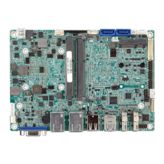
IEI Technology NANO-HM651 User Manual (165 pages)
EPIC SBC with Intel Celeron 847E Dual-Core CPU and Intel HM65 Chipset, DDR3, VGA, HDMI, USB 3.0, Dual PCle GbE, SATA 6Gb/s, HD Audio, RoHS Compliant
Brand:
IEI Technology
| Category:
Motherboard
| Size: 9 MB
Table of Contents
User Manual
1
Table of Contents
4
1 Introduction
15
Introduction
16
Connectors
17
Figure 1-2: Connectors
17
Dimensions
18
Figure 1-3: NANO-HM651 Dimensions (MM)
18
Data Flow
19
Figure 1-4: Data Flow Block Diagram
19
Technical Specifications
20
Table 1-1: Technical Specifications
21
2 Unpacking
22
Anti-Static Precautions
23
Unpacking Precautions
23
Unpacking Checklist
24
Package Contents
24
Optional Items
25
3 Connectors
26
Peripheral Interface Connectors
27
NANO-HM651 Layout
27
Figure 3-1: Connector and Jumper Locations
27
Peripheral Interface Connectors
28
Table 3-1: Peripheral Interface Connectors
28
External Interface Panel Connectors
29
Internal Peripheral Connectors
29
Audio Connector
29
Figure 1-1: NANO-HM651 EPIC SBC
29
Table 3-2: Rear Panel Connectors
29
Battery Connector
30
Figure 3-2: Audio Connector Location
30
Figure 3-3: Battery Connector Location
30
Table 3-3: Audio Connector Pinouts
30
Digital Input/Output (DIO) Connector
31
Figure 3-4: DIO Connector Location
31
Table 3-4: Battery Connector Pinouts
31
Table 3-5: DIO Connector Connector Pinouts
31
Debug Connector
32
Figure 3-5: EC Debug Connector Location
32
Table 3-6: Debug Connector Pinouts
32
Fan Connector (CPU)
33
Fan Connector (System)
33
Figure 3-6: CPU Fan Connector Location
33
Table 3-7: CPU Fan Connector Pinouts
33
Front Panel Connector
34
Figure 3-7: System Fan Connector Location
34
Table 3-8: System Fan Connector Pinouts
34
LVDS Backlight Inverter Connector
35
Figure 3-8: Front Panel Connector Location
35
Table 3-9: Front Panel Connector Pinouts
35
Keyboard/Mouse Connector
36
Figure 3-9: Backlight Inverter Connector Location
36
Table 3-10: Backlight Inverter Connector Pinouts
36
LVDS LCD Connector
37
Figure 3-10: Keyboard/Mouse Connector Location
37
Table 3-11: Keyboard/Mouse Connector Pinouts
37
Pcie Mini Card Slot
38
Figure 3-11: LVDS Connector Location
38
Table 3-12: LVDS Connector Pinouts
38
Figure 3-12: Pcie Mini Card Slot Location
39
Power Connector
40
Figure 3-13: CPU Power Connector Location
40
Table 3-13: Pcie Mini Card Slot Pinouts
40
SATA 6Gb/S Connector
41
Figure 3-14: SATA Drive Connector Locations
41
Table 3-14: CPU Power Connector Pinouts
41
Table 3-15: SATA Drive Connector Pinouts
41
SATA Power Connectors
42
Serial Port Connectors (COM 1 and COM 2)
42
Figure 3-15: SATA Power Connector Locations
42
Table 3-16: SATA Power Connector Pinouts
42
Serial Port Connector (COM3)
43
Figure 3-16: COM Connector Locations
43
Table 3-17: COM Connector Pinouts
43
Smbus Connector
44
Figure 3-17: Serial Port Connector Location
44
Table 3-18: Serial Port Connector Pinouts
44
Table 3-19: DB-9 RS-422/485 Pinouts
44
SPI Flash Connector
45
Figure 3-18: Smbus Connector Location
45
Table 3-20: Smbus Connector Pinouts
45
External Peripheral Interface Connector Panel
46
Figure 3-19: SPI Flash Connector Location
46
Figure 3-20: NANO-HM651 External Peripheral Interface Connector
46
Table 3-21: SPI Flash Connector
46
Ethernet Connectors
47
Figure 3-21: RJ-45 Ethernet Connector
47
Table 3-22: LAN Pinouts
47
Table 3-23: RJ-45 Ethernet Connector Leds
47
Figure 3-22: HDMI Connector
48
HDMI Connectors
48
Table 3-24: HDMI Connector Pinouts
48
USB 2.0 Connectors
48
Table 3-25: USB 2.0 Port Pinouts
49
Table 3-26: USB 3.0 Port Pinouts
49
USB 3.0 Connectors
49
Figure 3-23: VGA Connector
50
Table 3-27: VGA Connector Pinouts
50
VGA Connector
50
4 Installation
51
Anti-Static Precautions
52
Installation Considerations
53
So-DIMM Installation
54
Figure 4-1: SO-DIMM Installation
54
Pcie Mini Card Installation
55
Heat Sink Enclosure
55
Figure 4-2: Pcie Mini Card Installation
55
Figure 4-3: Heat Sink Retention Screws
56
Jumper Settings
57
AT/ATX Power Mode Select Jumper
57
Table 4-1: Jumpers
57
Clear CMOS Jumper
58
Figure 4-4: AT/ATX Power Mode Jumper Location
58
Table 4-2: AT/ATX Power Mode Jumper Settings
58
LVDS Voltage Selection Jumper
59
Figure 4-5: Clear CMOS Jumper
59
Table 4-3: Clear CMOS Jumper Settings
59
LVDS Panel Resolution Selection Jumper
60
Figure 4-6: LVDS Voltage Selection Jumper Location
60
Table 4-4: LVDS Voltage Selection Jumper Settings
60
TPM Setting Jumper
61
Figure 4-7: LVDS Screen Resolution Jumper Locations
61
Table 4-5: LVDS Screen Resolution Jumper Settings
61
Flash Descriptor Security Override Jumper
62
Figure 4-8: TPM Setting Jumper Location
62
Table 4-6: TPM Setting Jumper Settings
62
Table 4-7: Flash Descriptor Security Override Jumper Settings
62
Chassis Installation
63
Airflow
63
Motherboard Installation
63
Figure 4-9: Flash Descriptor Security Override Jumper Location
63
Internal Peripheral Device Connections
64
AT Power Connection
64
Figure 4-10: Power Cable to Motherboard Connection
65
Audio Kit Installation
66
Figure 4-11: Connect Power Cable to Power Supply
66
SATA Drive Connection
67
Figure 4-12: Audio Kit Cable Connection
67
Single RS-232 Cable
68
Figure 4-13: SATA Drive Cable Connection
68
USB Cable (Optional)
69
Figure 4-14: Single RS-232 Cable Installation
69
External Peripheral Interface Connection
70
Figure 4-15: Dual USB Cable Connection
70
Figure 4-16: HDMI Connection
71
HDMI Display Device Connection
71
Figure 4-17: LAN Connection
72
LAN Connection
72
USB Connection
72
Figure 4-18: USB Connector
73
VGA Monitor Connection
73
Software Installation
74
Figure 4-19: VGA Connector
74
Figure 4-20: Introduction Screen
75
Figure 4-21: Available Drivers
75
5 Bios Screens
76
Introduction
77
Starting Setup
77
Using Setup
77
Getting Help
78
Unable to Reboot after Configuration Changes
78
BIOS Menu Bar
78
Table 5-1: BIOS Navigation Keys
78
Main
79
BIOS Menu 1: Main
79
Advanced
80
ACPI Settings
80
BIOS Menu 2: Advanced
80
Trusted Computing
81
BIOS Menu 3: ACPI Configuration
81
CPU Configuration
82
BIOS Menu 4: TPM Configuration
82
BIOS Menu 5: CPU Configuration
83
SATA Configuration
84
BIOS Menu 6: SATA Configuration
84
USB Configuration
85
BIOS Menu 7: USB Configuration
85
Super IO Configuration
86
Serial Port N Configuration
86
BIOS Menu 8: Super IO Configuration
86
BIOS Menu 9: Serial Port N Configuration Menu
86
H/W Monitor
90
BIOS Menu 10: H/W Monitor
91
Smart Fan Mode Configuration
92
BIOS Menu 11: Smart Fan Mode Configuration
92
Serial Port Console Redirection
93
BIOS Menu 12: Serial Port Console Redirection
94
Sandybridge DTS Configuration
95
BIOS Menu 13: IEI Feature
95
Chipset
96
BIOS Menu 14: Chipset
96
Northbridge Configuration
97
BIOS Menu 15:Northbridge Configuration
97
Graphics Configuration
98
BIOS Menu 16:Graphics Configuration
98
Southbridge Configuration
100
BIOS Menu 17: Southbridge Chipset Configuration
100
Boot
102
BIOS Menu 18: Boot
102
Security
104
BIOS Menu 19: Security
104
Exit
105
BIOS Menu 20:Exit
105
ABIOS Options
107
B One Key Recovery
110
One Key Recovery Introduction
111
B.1 O Ne K Ey R Ecovery I Ntroduction
111
Figure B-1: IEI One Key Recovery Tool Menu
111
System Requirement
112
Supported Operating System
113
Setup Procedure for Windows
114
B.2 S Etup P Rocedure for W Indows
114
Create Partitions
115
Hardware and BIOS Setup
115
Figure B-2: Launching the Recovery Tool
116
Figure B-3: Recovery Tool Setup Menu
116
Figure B-4: Command Prompt
117
Figure B-5: Partition Creation Commands
118
Install Operating System, Drivers and Applications
119
Building the Recovery Partition
120
Figure B-6: Launching the Recovery Tool
120
Figure B-7: Manual Recovery Environment for Windows
120
Figure B-8: Building the Recovery Partition
121
Figure B-9: Press any Key to Continue
121
Create Factory Default Image
122
Figure B-10: Press F3 to Boot into Recovery Mode
122
Figure B-11: Recovery Tool Menu
122
Figure B-12: about Symantec Ghost Window
123
Figure B-13: Symantec Ghost Path
123
Figure B-14: Select a Local Source Drive
124
Figure B-15: Select a Source Partition from Basic Drive
124
Figure B-16: File Name to Copy Image to
125
Figure B-17: Compress Image
125
Figure B-18: Image Creation Confirmation
126
Figure B-19: Image Creation Complete
126
Figure B-20: Image Creation Complete
126
Auto Recovery Setup Procedure
127
Figure B-21: Press any Key to Continue
127
B.3 a Uto R Ecovery S Etup P Rocedure
127
Figure B-22: Auto Recovery Utility
128
Figure B-23: Disable Automatically Restart
128
Figure B-24: Launching the Recovery Tool
129
Figure B-25: Auto Recovery Environment for Windows
129
Figure B-26: Building the Auto Recovery Partition
130
Figure B-27: Factory Default Image Confirmation
130
Figure B-28: Image Creation Complete
131
Figure B-29: Press any Key to Continue
131
Setup Procedure for Linux
132
BIOS Menu 21: IEI Feature
132
B.4 S Etup P Rocedure for L Inux
132
Figure B-30: Partitions for Linux
133
Figure B-31: Manual Recovery Environment for Linux
134
Figure B-32: Access Menu.lst in Linux (Text Mode)
134
B.5 R Ecovery T Ool F Unctions
135
Figure B-34: Recovery Tool Main Menu
136
Factory Restore
137
Figure B-35: Restore Factory Default
137
Figure B-36: Recovery Complete Window
137
Backup System
138
Figure B-37: Backup System
138
Figure B-38: System Backup Complete Window
138
Figure B-39: Restore Backup
139
Figure B-40: Restore System Backup Complete Window
139
Restore Your Last Backup
139
Figure B-41: Symantec Ghost Window
140
Manual
140
Figure B-33: Recovery Tool Menu
135
Recovery Tool Functions
135
Restore Systems from a Linux Server through Lan
141
B.6 R Estore S Ystems from a L Inux S Erver through Lan
141
Configure DHCP Server Settings
142
Configure TFTP Settings
143
Configure One Key Recovery Server Settings
144
Create Shared Directory
145
Start the DHCP, TFTP and HTTP
145
Setup a Client System for Auto Recovery
146
Figure B-42: Disable Automatically Restart
147
Other Information
149
Using AHCI Mode or Ali M5283 / VIA VT6421A Controller
149
B.7 O Ther I Nformation
149
System Memory Requirement
151
C Terminology
152
D Digital I/O Interface
156
Introduction
157
Dio Connector Pinouts
157
D.1 I Ntroduction
157
Assembly Language Samples
158
Enable the DIO Input Function
158
Enable the DIO Output Function
158
D.3 a Ssembly L Anguage S Amples
158
E Watchdog Timer
159
F Hazardous Materials Disclosure
162
Ipb Products Certified as Ercury
163
Advertisement
Advertisement
Related Products
IEI Technology NANO-HM551
IEI Technology NANO-HM551-R10
IEI Technology NANO-HM650
IEI Technology NANO-HM650-R11
IEI Technology NANO-GM45A
IEI Technology NANO-QM871
IEI Technology NANO-4386A2
IEI Technology NANO-LX2
IEI Technology NANO-QM871-I1-I7-R11
IEI Technology NANO-GM45A2-R10
IEI Technology Categories
Motherboard
Touch Panel
Computer Hardware
Single board computers
Desktop
More IEI Technology Manuals
Login
Sign In
OR
Sign in with Facebook
Sign in with Google
Upload manual
Upload from disk
Upload from URL