Sign In
Upload
Manuals
Brands
IEI Technology Manuals
Motherboard
KINO-AA750-i2
IEI Technology KINO-AA750-i2 Manuals
Manuals and User Guides for IEI Technology KINO-AA750-i2. We have
1
IEI Technology KINO-AA750-i2 manual available for free PDF download: User Manual
IEI Technology KINO-AA750-i2 User Manual (193 pages)
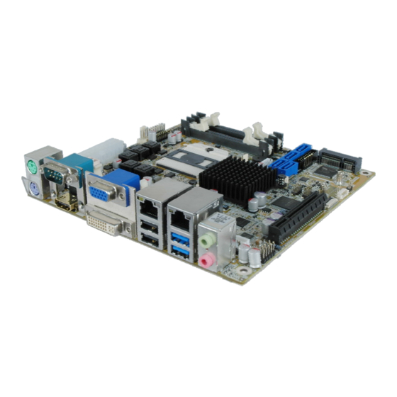
Mini-ITX SBC Supports Socket FS1r2 AMD R-Series APU, AMD A75 Chipset, DDR3, HDMI, DVI-D, VGA, iDP, Dual PCle GbE, SATA 6Gb/s, USB 3.0, PCle Mini, iRIS-2400, HD Audio and RoHS
Brand:
IEI Technology
| Category:
Motherboard
| Size: 9.41 MB
Table of Contents
Table of Contents
4
Introduction
16
Introduction
17
Figure 1-1: KINO-AA750-I2
17
Features
18
Connectors
19
Figure 1-2: Connectors (Front Side)
19
Figure 1-3: Connectors (Solder Side)
20
Dimensions
21
Figure 1-4: KINO-AA750-I2 Dimensions (MM)
21
Data Flow
22
Figure 1-5: Data Flow Diagram
22
Technical Specifications
23
Table 1-1: Technical Specifications
25
Packing List
26
Anti-Static Precautions
27
Unpacking Precautions
27
Packing List
28
Optional Items
29
Table 2-1: Packing List
29
Table 2-2: Optional Items
30
Connectors
31
Peripheral Interface Connectors
32
Layout
32
Figure 3-1: Peripheral Interface Connectors (Front Side)
32
Peripheral Interface Connectors
33
Figure 3-2: Peripheral Interface Connectors (Solder Side)
33
Table 3-1: Peripheral Interface Connectors
34
External Interface Panel Connectors
35
Internal Peripheral Connectors
35
ATX Power Connector
35
Table 3-2: Rear Panel Connectors
35
ATX Power Connector
36
Figure 3-3: +12V ATX Power Connector Location
36
Table 3-3: +12V ATX Power Connector Pinouts
36
Audio Amplifier Connector
37
Figure 3-4: ATX Power Connector Location
37
Table 3-4: ATX Power Connector Pinouts
37
Audio Connector
38
Figure 3-5: Audio Amplifier Connector Location
38
Table 3-5: Audio Amplifier Connector Pinouts
38
Battery Connector
39
Figure 3-6: Audio Connector Location
39
Table 3-6: Audio Connector Pinouts
39
Chassis Intrusion Connector
40
Figure 3-7: Battery Connector Location
40
Table 3-7: Battery Connector Pinouts
40
Digital I/O Connector
41
Figure 3-8: Chassis Intrusion Connector Location
41
Table 3-8: Chassis Intrusion Connector Pinouts
41
Fan Connector (CPU)
42
Figure 3-9: Digital I/O Connector Location
42
Table 3-9: Digital I/O Connector Pinouts
42
Fan Connector (System)
43
Figure 3-10: CPU Fan Connector Location
43
Table 3-10: CPU Fan Connector Pinouts
43
Front Panel Connector
44
Figure 3-11: System Fan Connector Location
44
Table 3-11: System Fan Connector Pinouts
44
Internal Displayport Connector
45
Figure 3-12: Front Panel Connector Location
45
Table 3-12: Front Panel Connector Pinouts
45
IPMI LED Connector
46
Figure 3-13: Internal Displayport Connector Location
46
Table 3-13: Internal Displayport Connector Pinouts
46
Iris Module Slot
47
Figure 3-14: IPMI LED Connector Location
47
Table 3-14: IPMI LED Connector Pinouts
47
LAN LED Connectors
48
Figure 3-15: Iris Module Slot Location
48
Pcie Mini Card Slot
49
Figure 3-16: LAN LED Connector Locations
49
Table 3-15: LAN LED Connector Pinouts
49
Figure 3-17: Pcie Mini Card Slot Location
50
Power Button (On-Board)
51
Figure 3-18: On-Board Power Button Location
51
Table 3-16: Pcie Mini Card Slot Pinouts
51
Reset Button (On-Board)
52
SATA 6Gb/S Drive Connectors
52
Figure 3-19: On-Board Reset Button Location
52
SD Card Slot
53
Figure 3-20: SATA 6Gb/S Drive Connector Locations
53
Table 3-17: SATA 6Gb/S Drive Connector Pinouts
53
Serial Port Connector, RS-232
54
Figure 3-21: SD Card Slot Location
54
Serial Port Connector, RS-422/485
55
Figure 3-22: RS-232 Serial Port Connector Location
55
Table 3-18: RS-232 Serial Port Connector Pinouts
55
Figure 3-23: RS-422/485 Serial Port Connector Location
56
Table 3-19: RS-422/485 Serial Port Connector Pinouts
56
Table 3-20: DB-9 RS-422/485 Pinouts
56
SIM Card Slot
57
Smbus Connector
57
Figure 3-24: SIM Card Slot Location
57
SO-DIMM Connectors
58
Figure 3-25: Smbus Connector Location
58
Table 3-21: Smbus Connector Pinouts
58
S/PDIF Connector
59
Figure 3-26: SO-DIMM Connector Locations
59
SPI Flash Connector
60
Figure 3-27: SPDIF Connector Location
60
Table 3-22: SPDIF Connector Pinouts
60
SPI Flash Connector (EC)
61
Figure 3-28: SPI Flash Connector Location
61
Table 3-23: SPI Flash Connector Pinouts
61
USB 2.0 Connectors
62
Figure 3-29: EC SPI Flash Connector Location
62
Table 3-24: EC SPI Flash Connector Pinouts
62
External Interface Connectors
63
Figure 3-30: USB Connector Locations
63
Figure 3-31: External Interface Connectors
63
Table 3-25: USB 2.0 Port Connector Pinouts
63
Audio Jacks
64
Ethernet and USB 2.0 Connectors
64
Figure 3-32: Audio Jacks
64
Ethernet and USB 3.0 Connectors
65
Table 3-26: LAN2 Pinouts
65
Table 3-27: External USB 2.0 Port Pinouts
65
Table 3-28: LAN1 Pinouts
65
HDMI Connector
66
Table 3-29: External USB 3.0 Port Pinouts
66
Keyboard and Mouse Connector
67
Serial Port Connector (COM1)
67
Table 3-30: HDMI Connector Pinouts
67
Table 3-31: PS/2 Connector Pinouts
67
VGA and DVI-D Connectors
68
Figure 3-33: Serial Port Pinouts
68
Table 3-32: Serial Port Pinouts
68
Figure 3-34: VGA Connector
69
Table 3-33: VGA Connector Pinouts
69
Table 3-34: DVI-D Connector Pinouts
69
Installation
70
Anti-Static Precautions
71
Installation Considerations
71
R 2 Cpu Installation
73
Figure 4-1: Unlocked Retention Screw
73
Figure 4-2: Lock the CPU Socket Retention Screw
74
Cooling Kit Installation
75
Figure 4-3: Install Support Bracket
75
Figure 4-4: Align the Cooling Kit
76
So-DIMM Installation
77
Figure 4-5: Secure the Cooling Kit
77
Figure 4-6: SO-DIMM Installation
77
Iris Module Installation
78
Figure 4-7: Iris Module Installation
78
Full-Size Pcie Mini Card Installation
79
Figure 4-8: Removing the Retention Screw
80
Figure 4-9: Inserting the Full-Size Pcie Mini Card into the Slot at an Angle
80
Half-Size Pcie Mini Card Installation
81
Figure 4-10: Securing the Full-Size Pcie Mini Card
81
Figure 4-11: Removing the Standoff
82
Figure 4-12: Installing the Standoff
82
Figure 4-13: Inserting the Half-Size Pcie Mini Card into the Slot at an Angle
83
Figure 4-14: Securing the Half-Size Pcie Mini Card
83
System Configuration
84
AT/ATX Power Mode Selection
84
Figure 4-15: AT/ATX Power Mode Switch Location
84
Table 4-1: AT/ATX Power Mode Switch Settings
84
Clear CMOS Button
85
Chassis Installation
85
Airflow
85
Figure 4-16: Clear CMOS Button Location
85
Motherboard Installation
86
Internal Peripheral Device Connections
86
SATA Drive Connection
86
Figure 4-17: SATA Drive Cable Connection
86
External Peripheral Interface Connection
87
Audio Connector
87
Figure 4-18: SATA Power Drive Connection
87
DVI Display Device Connection
88
Figure 4-19: Audio Connector
88
HDMI Display Device Connection
89
Figure 4-20: DVI-D Connector
89
LAN Connection
90
Figure 4-21: HDMI Connection
90
PS/2 Keyboard and Mouse Connection
91
Figure 4-22: LAN Connection
91
Serial Device Connection
92
Figure 4-23: PS/2 Keyboard/Mouse Connector
92
USB Connection
93
Figure 4-24: Serial Device Connector
93
VGA Monitor Connection
94
Figure 4-25: USB Connector
94
Ipmi Setup Procedure
95
Managed System Hardware Setup
95
Figure 4-26: VGA Connector
95
Using the IEI Iman Web GUI
96
Figure 4-27: IEI Iman Web Address
96
Figure 4-28: IEI Iman Web GUI
97
Bios
98
Introduction
99
Starting Setup
99
Using Setup
99
Getting Help
100
Unable to Reboot after Configuration Changes
100
BIOS Menu Bar
100
Table 5-1: BIOS Navigation Keys
100
Main
101
BIOS Menu 1: Main
101
Advanced
102
ACPI Settings
102
BIOS Menu 2: Advanced
102
Trusted Computing
103
BIOS Menu 3: ACPI Settings
103
RTC Wake Settings
104
BIOS Menu 4: Trusted Computing
104
BIOS Menu 5: RTC Wake Settings
105
CPU Configuration
106
BIOS Menu 6: CPU Configuration
106
Node 0 Information
107
IDE Configuration
107
BIOS Menu 7: Node 0 Information
107
BIOS Menu 8: IDE Configuration
107
USB Configuration
108
BIOS Menu 9: USB Configuration
108
Iwdd H/W Monitor
109
BIOS Menu 10: Iwdd H/W Monitor
109
Smart Fan Mode Configuration
110
BIOS Menu 11: Smar Fan Mode Configuration
110
F81866 Super IO Configuration
111
BIOS Menu 12: F81866 Super IO Configuration
111
Serial Port N Configuration
112
BIOS Menu 13: Serial Port N Configuration Menu
112
F81866 H/W Monitor
115
Serial Port Console Redirection
115
BIOS Menu 14: F81866 H/W Monitor
115
BIOS Menu 15: Serial Port Console Redirection
116
Chipset
118
BIOS Menu 16: Chipset
118
Southbridge Configuration
119
BIOS Menu 17: Southbridge Configuration
119
SB SATA Configuration
120
BIOS Menu 18: SB SATA Configuration
120
SB HD Azalia Configuration
121
BIOS Menu 19: SB HD Azalia Configuration Menu
121
Northbridge Configuration
122
Socket 0 Information
122
BIOS Menu 20: Northbridge Configuration
122
BIOS Menu 21: Socket 0 Information
122
Boot
123
BIOS Menu 22: Boot
123
Security
125
Save & Exit
125
BIOS Menu 23: Security
125
BIOS Menu 24: Save & Exit
126
Software Drivers
127
Available Software Drivers
128
Starting the Driver Program
128
Graphics Driver Installation
129
Figure 6-1: Graphics Driver Welcome Screen
129
Figure 6-2: Select Installation Operation Screen
130
Figure 6-3: Select Express or Custom Install Screen
130
Figure 6-4: Graphics Driver License Agreement
131
Figure 6-5: Graphics Driver Setup Operations
131
Lan Driver Installation
132
Figure 6-6: Graphics Driver Installation Finished Screen
132
Figure 6-7: Reboot Screen
132
Figure 6-8: Intel® Network Connection Menu
133
Figure 6-9: LAN Driver Welcome Screen
133
Figure 6-10: LAN Driver License Agreement
134
Figure 6-11: LAN Driver Setup Options
134
Figure 6-12: LAN Driver Installation
135
Figure 6-13: LAN Driver Installation Complete
135
Audio Driver Installation
136
Figure 6-14: Audio Driver Welcome Screen
136
Figure 6-15: Audio Driver Installation
137
Figure 6-16: Audio Driver Installation Complete
137
ABIOS Options
138
B One Key Recovery
141
One Key Recovery Introduction
142
Figure B-1: IEI One Key Recovery Tool Menu
142
System Requirement
143
Supported Operating System
144
Setup Procedure for Windows
145
Hardware and BIOS Setup
146
Create Partitions
146
Figure B-2: Launching the Recovery Tool
147
Figure B-3: Recovery Tool Setup Menu
147
Figure B-4: Command Prompt
148
Figure B-5: Partition Creation Commands
149
Install Operating System, Drivers and Applications
150
Building the Recovery Partition
151
Figure B-6: Launching the Recovery Tool
151
Figure B-7: Manual Recovery Environment for Windows
151
Figure B-8: Building the Recovery Partition
152
Figure B-9: Press any Key to Continue
152
Create Factory Default Image
153
Figure B-10: Press F3 to Boot into Recovery Mode
153
Figure B-11: Recovery Tool Menu
153
Figure B-12: about Symantec Ghost Window
154
Figure B-13: Symantec Ghost Path
154
Figure B-14: Select a Local Source Drive
155
Figure B-15: Select a Source Partition from Basic Drive
155
Figure B-16: File Name to Copy Image to
156
Figure B-17: Compress Image
156
Figure B-18: Image Creation Confirmation
157
Figure B-19: Image Creation Complete
157
Figure B-20: Image Creation Complete
157
Auto Recovery Setup Procedure
158
Figure B-21: Press any Key to Continue
158
Figure B-22: Auto Recovery Utility
159
Figure B-23: Disable Automatically Restart
159
Figure B-24: Launching the Recovery Tool
160
Figure B-25: Auto Recovery Environment for Windows
160
Figure B-26: Building the Auto Recovery Partition
161
Figure B-27: Factory Default Image Confirmation
161
Figure B-28: Image Creation Complete
162
Figure B-29: Press any Key to Continue
162
Setup Procedure for Linux
163
Figure B-30: IEI Feature
163
Figure B-31: Partitions for Linux
164
Figure B-32: Manual Recovery Environment for Linux
165
Figure B-33: Access Menu.lst in Linux (Text Mode)
165
Recovery Tool Functions
166
Figure B-34: Recovery Tool Menu
166
Figure B-35: Recovery Tool Main Menu
167
Factory Restore
168
Figure B-36: Restore Factory Default
168
Figure B-37: Recovery Complete Window
168
Backup System
169
Figure B-38: Backup System
169
Figure B-39: System Backup Complete Window
169
Restore Your Last Backup
170
Figure B-40: Restore Backup
170
Figure B-41: Restore System Backup Complete Window
170
Manual
171
Figure B-42: Symantec Ghost Window
171
Restore Systems from a Linux Server through Lan
172
Configure DHCP Server Settings
173
Configure TFTP Settings
174
Configure One Key Recovery Server Settings
175
Start the DHCP, TFTP and HTTP
176
Create Shared Directory
176
Setup a Client System for Auto Recovery
177
Figure B-43: Disable Automatically Restart
178
Other Information
180
Using AHCI Mode or Ali M5283 / VIA VT6421A Controller
180
System Memory Requirement
182
C Terminology
183
D Digital I/O Interface
187
Introduction
188
Dio Connector Pinouts
188
Assembly Language Samples
188
Enable the DIO Input Function
188
Table 6-1: Digital I/O Connector Pinouts
188
Enable the DIO Output Function
189
E Hazardous Materials Disclosure
190
Hazardous Materials Disclosure Table for IPB Products Certified as Rohs Compliant under 2002/95/EC Without Mercury
191
Advertisement
Advertisement
Related Products
IEI Technology KINO-AH612
IEI Technology KINO-AQ670
IEI Technology KINO-ATOM
IEI Technology KINO-AH611
IEI Technology KINO-AQ170
IEI Technology KINO-ADL-P
IEI Technology KINO-ADL-P-C-R10
IEI Technology KINO-ADL-P-i3-R10
IEI Technology KINO-ADL-P-i5-R10
IEI Technology KINO-ADL-P-i7-R10
IEI Technology Categories
Motherboard
Touch Panel
Computer Hardware
Single board computers
Desktop
More IEI Technology Manuals
Login
Sign In
OR
Sign in with Facebook
Sign in with Google
Upload manual
Upload from disk
Upload from URL