IEI Technology KINO-780AM2 Manuals
Manuals and User Guides for IEI Technology KINO-780AM2. We have 2 IEI Technology KINO-780AM2 manuals available for free PDF download: User Manual
IEI Technology KINO-780AM2 User Manual (131 pages)
Mini-ITX AMD Socket AM2 with VGA, DVI-I and HDMI Dual PCIe, USB 2.0, SATA II and Aud
Brand: IEI Technology
|
Category: Motherboard
|
Size: 5.09 MB
Table of Contents
Advertisement

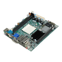
IEI Technology KINO-780AM2 User Manual (131 pages)
Mini-ITX AMD Socket AM2 with VGA, DVI-I and HDMI Dual PCIe, USB 2.0, SATA II and Audio
Brand: IEI Technology
|
Category: Motherboard
|
Size: 2.98 MB