Sign In
Upload
Manuals
Brands
IEI Technology Manuals
Motherboard
IMBA-G410
IEI Technology IMBA-G410 ATX Motherboard Manuals
Manuals and User Guides for IEI Technology IMBA-G410 ATX Motherboard. We have
3
IEI Technology IMBA-G410 ATX Motherboard manuals available for free PDF download: User Manual, Quick Installation Manual
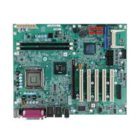
IEI Technology IMBA-G410 User Manual (165 pages)
ATX motherboard for Intel Core 2 Duo/Quad CPU, 800/1066/1333 MHz FSB, DDR3, VGA, LAN, SATA 3Gb/x, PCIe x16, PCIe x4, PCI, USB, HD Audio, RoHS Compliant
Brand:
IEI Technology
| Category:
Motherboard
| Size: 4.41 MB
Table of Contents
Table of Contents
4
Introduction
15
Introduction
16
Benefits
16
Figure 1-1: IMBA-G410
16
Features
17
Connectors
18
Figure 1-2: Connectors
18
Dimensions
19
Figure 1-3: Dimensions (MM)
19
Data Flow
20
Figure 1-4: Data Flow Diagram
20
Technical Specifications
21
Table 1-1: Technical Specifications
22
Packing List
23
Anti Static Precautions
24
Unpacking Precautions
24
Packing List
25
Optional Items
26
Table 2-1: Packing List
26
Table 2-2: Optional Items
27
Connectors
28
Peripheral Interface Connectors
29
Layout
29
Figure 3-1: Connectors and Jumpers
29
Peripheral Interface Connectors
30
External Interface Panel Connectors
31
Internal Peripheral Connectors
31
Audio Connector
31
Table 3-1: Internal Peripheral Connectors
31
Table 3-2: External Peripheral Connectors
31
CPU Fan Connector
32
Figure 3-2: Audio Connector Location
32
Table 3-3: Audio Connector Pinouts
32
Figure 3-3: CPU Fan Connector Location
33
Figure 3-4: System Fan Connector Locations
33
System Fan Connectors
33
Table 3-4: CPU Fan Connector Pinouts
33
CPU Power Input Connector
34
Figure 3-5: CPU Power Input Connector Location
34
Table 3-5: System Fan Connector Pinouts (SYS_FAN1)
34
Table 3-6: System Fan Connector Pinouts (SYS_FAN2 and SYS_FAN3)
34
Table 3-7: CPU Power Input Connector Pinouts
34
Digital I/O Connector
35
Figure 3-6: Digital I/O Connector Location
35
Front Panel Connector
35
Table 3-8: Digital I/O Connector Pinouts
35
Figure 3-7: Front Panel Connector Location
36
IDE Connector
36
Table 3-9: Front Panel Connector Pinouts
36
Figure 3-8: IDE Connector Location
37
Table 3-10: IDE Connector Pinouts
37
Figure 3-9: Infrared Connector Location
38
Infrared Interface Connector
38
Memory Slots
38
Table 3-11: Infrared Connector Pinouts
38
Figure 3-10: Memory Card Slot Locations
39
Figure 3-11: Pcie Power Input Connector Location
39
Pcie Power Input Connector
39
Table 3-12: Pcie Power Input Connector Pinouts
39
Figure 3-12: Power Connector Location
40
Power Connector
40
Table 3-13: Power Connector Pinouts
40
Figure 3-13: Serial Port Connector Locations
41
Serial Port Connectors
41
Table 3-14: Serial Port Connector Pinouts
41
Figure 3-14: RS-232/422/485 Serial Port Connector Location
42
RS-232/422/485 Serial Port Connector
42
SATA Drive Connectors
42
Table 3-15: RS-232/422/485 Serial Port Connector Pinouts
42
Figure 3-15: SATA Drive Connector Locations
43
Figure 3-16: Smbus Connector Location
43
Smbus Connector
43
Figure 3-17: SPDIF Connector Location
44
SPDIF Connector
44
Table 3-16: Smbus Connector Pinouts
44
Table 3-17: SPDIF Connector Pinouts
44
Figure 3-18: SPI Flash Connector Location
45
SPI Flash Connector
45
Table 3-18: SPI Flash Connector
45
TPM Connector
45
Figure 3-19: TPM Connector Pinout Location
46
Table 3-19: TPM Connector Pinouts
46
USB Connectors
46
External Peripheral Interface Connector Panel
47
Figure 3-20: USB Connector Pinout Locations
47
Figure 3-21: External Peripheral Interface Connector
47
Table 3-20: USB Port Connector Pinouts
47
Audio Connectors
48
Figure 3-22: Audio Connector
48
Keyboard/Mouse Connector
48
Figure 3-23: PS/2 Pinout and Configuration
49
LAN Connectors
49
Table 3-21: Keyboard Connector Pinouts
49
Parallel Port Connector
50
Table 3-22: LAN Pinouts
50
Serial Port Connector (COM1)
51
Figure 3-24: Parallel Port Connector Location
51
Table 3-23: Parallel Port Connector Pinouts
51
Table 3-24: Serial Port Pinouts
51
Figure 3-25: Serial Port Pinouts
52
Table 3-25: USB Port Pinouts
52
USB Connectors
52
VGA Connector
52
Figure 3-26: VGA Connector
53
Table 3-26: VGA Connector Pinouts
53
Installation
54
Anti - Static Precautions
55
Installation Considerations
55
Basic Installation
57
CPU Installation
57
Figure 4-1: Intel LGA775 Socket
57
Figure 4-2: Remove Protective Cover
58
Figure 4-3: CPU Socket Load Plate
58
Figure 4-4: Insert the Socket LGA775 CPU
59
Cooling Kit Installation
60
Figure 4-5: Cooling Kits
60
Figure 4-6: Securing the Heat Sink to the IMBA-G410
61
DIMM Installation
62
Motherboard Installation
62
Figure 4-7: DIMM Installation
62
Jumper Settings
63
AT/ATX Power Select Jumpers
63
Table 4-1: Jumpers
63
Clear CMOS Jumper
64
Figure 4-8: AT/ATX Power Select Jumper Location
64
Table 4-2: AT/ATX Power Select Jumper Settings
64
Table 4-3: Clear BIOS Jumper Settings
64
COM 2 Function Select Jumper
65
Figure 4-9: Clear BIOS Jumper Location
65
Table 4-4: COM 2 Function Select Jumper Settings
65
Compactflash® Setup
66
Figure 4-10: COM 2 Function Select Jumper Location
66
Figure 4-11: Compactflash® Setup Jumper Location
66
Table 4-5: Compactflash® Setup Jumper Settings
66
CF Voltage Select Jumper
67
USB Power Select Jumpers
67
Figure 4-12: LCD Voltage Selection Jumper Location
67
Table 4-6: LCD Voltage Selection Jumper Settings
67
Internal Peripheral Device Connections
68
SATA Drive Connection
68
Figure 4-13: USB Power Select Jumper Location
68
Table 4-7: USB Power Select Jumper Settings
68
Figure 4-14: SATA Drive Cable Connection
69
Dual RS-232 Cable with Slot Bracket
70
Figure 4-15: SATA Power Drive Connection
70
External Peripheral Interface Connection
71
Audio Connector
71
Figure 4-16: Dual RS-232 Cable Installation
71
PS/2 Keyboard and Mouse Connection
72
Figure 4-17: Audio Connector
72
LAN Connection
73
Figure 4-18: PS/2 Keyboard/Mouse Connector
73
Parallel Device Connection
74
Figure 4-19: LAN Connection
74
Serial Device Connection
75
Figure 4-20: Parallel Device Connector
75
USB Device Connection
76
Figure 4-21: Serial Device Connector
76
VGA Monitor Connection
77
Figure 4-22: USB Connector
77
Software Installation
78
Figure 4-23: VGA Connector
78
Bios
79
5 Bios
80
Introduction
80
Starting Setup
80
Using Setup
80
Getting Help
81
Unable to Reboot after Configuration Changes
81
BIOS Menu Bar
81
Table 5-1: BIOS Navigation Keys
81
Main
82
Advanced
83
CPU Configuration
84
IDE Configuration
84
IDE Master, IDE Slave
86
Super IO Configuration
92
Hardware Health Configuration
97
Power Configuration
100
ACPI Configuration
101
APM Configuration
101
Remote Access Configuration
103
USB Configuration
106
Trusted Computing
107
Pci/P N P
108
Boot
111
Boot Settings Configuration
111
Security
113
Chipset
115
North Bridge Chipset Configuration
115
South Bridge Chipset Configuration
118
Exit
119
A Bios Options
121
B Terminology
125
C One Key Recovery
129
One Key Recovery Introduction
130
C.1 O Ne K Ey R Ecovery I Ntroduction
130
Figure C-1: IEI One Key Recovery Tool Menu
130
System Requirement
131
Supported Operating System
132
Setup Procedure for Windows
133
Hardware and BIOS Setup
133
C.2 S Etup P Rocedure for W Indows
133
Create Partitions
134
Figure C-2: Launching the Recovery Tool
134
Figure C-3: Recovery Tool Setup Menu
135
Figure C-4: Command Mode
135
Figure C-5: Partition Creation Commands
136
Install Operating System, Drivers and Applications
137
Build-Up Recovery Partition
138
Figure C-6: Launching the Recovery Tool
138
Figure C-7: System Configuration for Windows
138
Figure C-8: Build-Up Recovery Partition
139
Figure C-9: Press any Key to Continue
139
Create Factory Default Image
140
Figure C-10: Press F3 to Boot into Recovery Mode
140
Figure C-11: Recovery Tool Menu
140
Figure C-12: about Symantec Ghost Window
141
Figure C-13: Symantec Ghost Path
141
Figure C-14: Select a Local Source Drive
142
Figure C-15: Select a Source Partition from Basic Drive
142
Figure C-16: File Name to Copy Image to
143
Figure C-17: Compress Image
143
Figure C-18: Image Creation Confirmation
144
Figure C-19: Image Creation Process
144
Figure C-20: Image Creation Complete
144
C.3 S Etup P Rocedure for L Inux
145
Figure C-21: Press any Key to Continue
145
Setup Procedure for Linux
145
Figure C-22: Partitions for Linux
146
Figure C-23: System Configuration for Linux
147
Figure C-24: Access Menu.lst in Linux (Text Mode)
147
C.4 R Ecovery T Ool F Unctions
148
Figure C-26: Recovery Tool Main Menu
149
Factory Restore
150
Figure C-27: Restore Factory Default
150
Figure C-28: Recovery Complete Window
150
Backup System
151
Figure C-29: Backup System
151
Figure C-30: System Backup Complete Window
151
Figure C-31: Restore Backup
152
Figure C-32: Restore System Backup Complete Window
152
Restore Your Last Backup
152
Figure C-33: Symantec Ghost Window
153
Manual
153
Figure C-25: Recovery Tool Menu
148
Recovery Tool Functions
148
Other Information
154
Using AHCI Mode or Ali M5283 / VIA VT6421A Controller
154
C.5 O Ther I Nformation
154
System Memory Requirement
156
D Watchdog Timer
157
E Digital I/O Interface
160
Introduction
161
Dio Connector Pinouts
161
Assembly Language Example
161
E.1 I Ntroduction
161
F Hazardous Materials Disclosure
162
Advertisement
IEI Technology IMBA-G410 User Manual (158 pages)
ATX motherboard for intel core 2 duo/quad CPU
Brand:
IEI Technology
| Category:
Motherboard
| Size: 7.84 MB
Table of Contents
User Manual
1
Table of Contents
4
1 Introduction
15
Introduction
16
Benefits
16
Figure 1-1: IMBA-G410
16
Features
17
Connectors
18
Figure 1-2: Connectors
18
Dimensions
19
Figure 1-3: Dimensions (MM)
19
Data Flow
20
Figure 1-4: Data Flow Diagram
20
Technical Specifications
21
Table 1-1: Technical Specifications
22
2 Packing List
23
Anti-Static Precautions
24
Unpacking Precautions
24
Packing List
25
Optional Items
26
Table 2-1: Packing List
26
Table 2-2: Optional Items
27
3 Connectors
28
Peripheral Interface Connectors
29
Layout
29
Figure 3-1: Connectors and Jumpers
29
Peripheral Interface Connectors
30
External Interface Panel Connectors
31
Internal Peripheral Connectors
31
Audio Connector
31
Table 3-1: Internal Peripheral Connectors
31
Table 3-2: External Peripheral Connectors
31
CPU Fan Connector
32
Figure 3-2: Audio Connector Location
32
Table 3-3: Audio Connector Pinouts
32
System Fan Connectors
33
Figure 3-3: CPU Fan Connector Location
33
Figure 3-4: System Fan Connector Locations
33
Table 3-4: CPU Fan Connector Pinouts
33
CPU Power Input Connector
34
Figure 3-5: CPU Power Input Connector Location
34
Table 3-5: System Fan Connector Pinouts (SYS_FAN1)
34
Table 3-6: System Fan Connector Pinouts (SYS_FAN2 and SYS_FAN3)
34
Table 3-7: CPU Power Input Connector Pinouts
34
Digital I/O Connector
35
Front Panel Connector
35
Figure 3-6: Digital I/O Connector Location
35
Table 3-8: Digital I/O Connector Pinouts
35
IDE Connector
36
Figure 3-7: Front Panel Connector Location
36
Table 3-9: Front Panel Connector Pinouts
36
Figure 3-8: IDE Connector Location
37
Table 3-10: IDE Connector Pinouts
37
Infrared Interface Connector
38
Memory Slots
38
Figure 3-9: Infrared Connector Location
38
Table 3-11: Infrared Connector Pinouts
38
Pcie Power Input Connector
39
Figure 3-10: Memory Card Slot Locations
39
Figure 3-11: Pcie Power Input Connector Location
39
Table 3-12: Pcie Power Input Connector Pinouts
39
Power Connector
40
Figure 3-12: Power Connector Location
40
Table 3-13: Power Connector Pinouts
40
Serial Port Connectors
41
Figure 3-13: Serial Port Connector Locations
41
Table 3-14: Serial Port Connector Pinouts
41
RS-232/422/485 Serial Port Connector
42
SATA Drive Connectors
42
Figure 3-14: RS-232/422/485 Serial Port Connector Location
42
Table 3-15: RS-232/422/485 Serial Port Connector Pinouts
42
Smbus Connector
43
Figure 3-15: SATA Drive Connector Locations
43
Figure 3-16: Smbus Connector Location
43
SPDIF Connector
44
Figure 3-17: SPDIF Connector Location
44
Table 3-16: Smbus Connector Pinouts
44
Table 3-17: SPDIF Connector Pinouts
44
SPI Flash Connector
45
TPM Connector
45
Figure 3-18: SPI Flash Connector Location
45
Table 3-18: SPI Flash Connector
45
USB Connectors
46
Figure 3-19: TPM Connector Pinout Location
46
Table 3-19: TPM Connector Pinouts
46
External Peripheral Interface Connector Panel
47
Figure 3-20: USB Connector Pinout Locations
47
Figure 3-21: External Peripheral Interface Connector
47
Table 3-20: USB Port Connector Pinouts
47
Audio Connectors
48
Figure 3-22: Audio Connector
48
Keyboard/Mouse Connector
48
Figure 3-23: PS/2 Pinout and Configuration
49
LAN Connectors
49
Table 3-21: Keyboard Connector Pinouts
49
Parallel Port Connector
50
Table 3-22: LAN Pinouts
50
Figure 3-24: Parallel Port Connector Location
51
Serial Port Connector (COM1)
51
Table 3-23: Parallel Port Connector Pinouts
51
Table 3-24: Serial Port Pinouts
51
Figure 3-25: Serial Port Pinouts
52
Table 3-25: USB Port Pinouts
52
USB Connectors
52
VGA Connector
52
Figure 3-26: VGA Connector
53
Table 3-26: VGA Connector Pinouts
53
4 Installation
54
Anti-Static Precautions
55
Installation Considerations
55
Basic Installation
57
CPU Installation
57
Figure 4-1: Intel LGA775 Socket
57
Figure 4-2: Remove Protective Cover
58
Figure 4-3: CPU Socket Load Plate
58
Figure 4-4: Insert the Socket LGA775 CPU
59
Cooling Kit Installation
60
Figure 4-5: Cooling Kits
60
Figure 4-6: Securing the Heat Sink to the IMBA-G410
61
DIMM Installation
62
Motherboard Installation
62
Figure 4-7: DIMM Installation
62
Jumper Settings
63
AT/ATX Power Select Jumpers
63
Table 4-1: Jumpers
63
Clear CMOS Jumper
64
Figure 4-8: AT/ATX Power Select Jumper Location
64
Table 4-2: AT/ATX Power Select Jumper Settings
64
Table 4-3: Clear BIOS Jumper Settings
64
COM 2 Function Select Jumper
65
Figure 4-9: Clear BIOS Jumper Location
65
Table 4-4: COM 2 Function Select Jumper Settings
65
Compactflash® Setup
66
Figure 4-10: COM 2 Function Select Jumper Location
66
Figure 4-11: Compactflash® Setup Jumper Location
66
Table 4-5: Compactflash® Setup Jumper Settings
66
CF Voltage Select Jumper
67
USB Power Select Jumpers
67
Figure 4-12: LCD Voltage Selection Jumper Location
67
Table 4-6: LCD Voltage Selection Jumper Settings
67
Internal Peripheral Device Connections
68
SATA Drive Connection
68
Figure 4-13: USB Power Select Jumper Location
68
Table 4-7: USB Power Select Jumper Settings
68
Figure 4-14: SATA Drive Cable Connection
69
Dual RS-232 Cable with Slot Bracket
70
Figure 4-15: SATA Power Drive Connection
70
External Peripheral Interface Connection
71
Audio Connector
71
Figure 4-16: Dual RS-232 Cable Installation
71
PS/2 Keyboard and Mouse Connection
72
Figure 4-17: Audio Connector
72
LAN Connection
73
Figure 4-18: PS/2 Keyboard/Mouse Connector
73
Parallel Device Connection
74
Figure 4-19: LAN Connection
74
Serial Device Connection
75
Figure 4-20: Parallel Device Connector
75
USB Device Connection
76
Figure 4-21: Serial Device Connector
76
VGA Monitor Connection
77
Figure 4-22: USB Connector
77
Software Installation
78
Figure 4-23: VGA Connector
78
5 Bios
79
Introduction
80
Starting Setup
80
Using Setup
80
Getting Help
81
Unable to Reboot after Configuration Changes
81
Main Bios Menu
81
Table 5-1: BIOS Navigation Keys
81
BIOS Menu 1: BYOSOFT BIOS Setup Utility
82
Standard Bios Features
84
System Information
85
Advanced Bios Features
86
SATA Configuration
86
Onboard Devices Configuration
87
BIOS Menu 6: Onboard Devices Configuration
88
Console Redirection Configuration
95
BIOS Menu 7: Console Redirection Configuration
96
Advanced Chipset Features
97
BIOS Menu 8: Advanced Chipset Features
98
Boot Configuration Features
100
Boot Settings Configuration
101
Boot Device Priority
103
Subdevice Boot Configuration
104
Power Management Features
104
BIOS Menu 13: Power Management Features
105
APM Configuration
106
Pnp/Pci Configurations
108
Pc Health Status
110
PC Health Info
110
BIOS Menu 17: PC Health Status
111
Bios Security Features
112
BIOS Menu 18: BIOS Security Features
112
System Configuration Lock
113
HDD Security
114
ABIOS Options
115
B Terminology
118
C One Key Recovery
122
One Key Recovery Introduction
123
C.1 O Ne K Ey R Ecovery I Ntroduction
123
Figure C-1: IEI One Key Recovery Tool Menu
123
System Requirement
124
Supported Operating System
125
Setup Procedure for Windows
126
Hardware and BIOS Setup
126
Create Partitions
127
Figure C-2: Launching the Recovery Tool
127
Figure C-3: Recovery Tool Setup Menu
128
Figure C-4: Command Mode
128
Figure C-5: Partition Creation Commands
129
Install Operating System, Drivers and Applications
130
Build-Up Recovery Partition
131
Figure C-6: Launching the Recovery Tool
131
Figure C-7: System Configuration for Windows
131
Figure C-8: Build-Up Recovery Partition
132
Figure C-9: Press any Key to Continue
132
Create Factory Default Image
133
Figure C-10: Press F3 to Boot into Recovery Mode
133
Figure C-11: Recovery Tool Menu
133
Figure C-12: about Symantec Ghost Window
134
Figure C-13: Symantec Ghost Path
134
Figure C-14: Select a Local Source Drive
135
Figure C-15: Select a Source Partition from Basic Drive
135
Figure C-16: File Name to Copy Image to
136
Figure C-17: Compress Image
136
Figure C-18: Image Creation Confirmation
137
Figure C-19: Image Creation Process
137
Figure C-20: Image Creation Complete
137
Setup Procedure for Linux
138
Figure C-21: Press any Key to Continue
138
Figure C-22: Partitions for Linux
139
Figure C-23: System Configuration for Linux
140
Figure C-24: Access Menu.lst in Linux (Text Mode)
140
Recovery Tool Functions
141
Figure C-25: Recovery Tool Menu
141
C.4 R Ecovery T Ool F Unctions
141
Figure C-26: Recovery Tool Main Menu
142
Factory Restore
143
Figure C-27: Restore Factory Default
143
Figure C-28: Recovery Complete Window
143
Backup System
144
Figure C-29: Backup System
144
Figure C-30: System Backup Complete Window
144
Figure C-31: Restore Backup
145
Figure C-32: Restore System Backup Complete Window
145
Restore Your Last Backup
145
Figure C-33: Symantec Ghost Window
146
Manual
146
Other Information
147
Using AHCI Mode or Ali M5283 / VIA VT6421A Controller
147
C.5 O Ther I Nformation
147
System Memory Requirement
149
D Watchdog Timer
150
E Digital I/O Interface
153
Introduction
154
Dio Connector Pinouts
154
Assembly Language Example
154
E.1 I Ntroduction
154
F Hazardous Materials Disclosure
155
Hazardous Materials Disclosure Table for IPB Products Certified as Rohs Compliant under 2002/95/EC Without Mercury
156
IEI Technology IMBA-G410 Quick Installation Manual (12 pages)
ATX Motherboard supports LGA775 Intel Core 2 Dual/Quad CPU with 1333/1066/800MHz FSB, VGA, PCIe x16, PCIe x4(x1 signal), PCI, 6COM, Dual PCIe GbE, USB2.0, CF, SATAII and Audio, RoHS
Brand:
IEI Technology
| Category:
Motherboard
| Size: 0.15 MB
Advertisement
Advertisement
Related Products
IEI Technology IMBA-G412ISA
IEI Technology IMBA-G412ISA-R20
IEI Technology IMBA-9454G
IEI Technology IMBA-C604EN
IEI Technology IMBA-BDE-1518
IEI Technology IMBA-Q370-R20
IEI Technology IMBA-BDE-D1518-R10
IEI Technology IMBA-BDE
IEI Technology IMBA-C2160-R10
IEI Technology IMBA-C2460
IEI Technology Categories
Motherboard
Touch Panel
Computer Hardware
Single board computers
Desktop
More IEI Technology Manuals
Login
Sign In
OR
Sign in with Facebook
Sign in with Google
Upload manual
Upload from disk
Upload from URL