Sign In
Upload
Manuals
Brands
IEI Technology Manuals
Motherboard
IMBA-BDE-D1518-R10
IEI Technology IMBA-BDE-D1518-R10 Manuals
Manuals and User Guides for IEI Technology IMBA-BDE-D1518-R10. We have
1
IEI Technology IMBA-BDE-D1518-R10 manual available for free PDF download: User Manual
IEI Technology IMBA-BDE-D1518-R10 User Manual (119 pages)
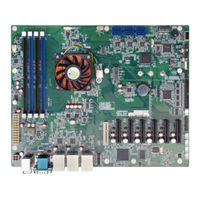
ATX Motherboard with 14nm Intel Xeon Processor D-1500 Series, DDR4, VGA, DualIntel GbE, Four USB 3.0, Six SATA 6Gb/s, M.2, Supports Dual 10GbE, RoHS
Brand:
IEI Technology
| Category:
Motherboard
| Size: 5.57 MB
Table of Contents
Table of Contents
5
Introduction
14
Introduction
15
Figure 1-1: IMBA-BDE
15
Model Variations
16
Features
16
Table 1-1: Model Variations
16
Connectors
17
Figure 1-2: Connectors
17
Dimensions
18
Figure 1-3: IMBA-BDE Dimensions (MM)
18
Data Flow
19
Figure 1-4: Data Flow Diagram
19
Technical Specifications
20
Table 1-2: Technical Specifications
21
Packing List
22
Anti-Static Precautions
23
Unpacking Precautions
23
Packing List
24
Table 2-1: Packing List
24
Optional Items
25
Table 2-2: Optional Items
25
Connectors
26
Peripheral Interface Connectors
27
Layout
27
Figure 3-1: Peripheral Interface Connectors
27
Peripheral Interface Connectors
28
External Interface Panel Connectors
29
Table 3-1: Peripheral Interface Connectors
29
Table 3-2: Rear Panel Connectors
29
Internal Peripheral Connectors
30
ATX Power Connector
30
Figure 3-2: +12V ATX Power Connector Location
30
Table 3-3: +12V ATX Power Connector Pinouts
30
10Gbe LAN Card Slot
31
Figure 3-3: 10Gbe LAN Card Slot Location
31
ATX Power Connector
32
Figure 3-4: ATX Power Connector Location
32
Table 3-4: ATX Power Connector Pinouts
32
Battery Connector
33
Figure 3-5: Battery Connector Location
33
BMC Debug Connector
34
Figure 3-6: BMC Debug Connector Location
34
Table 3-5: BMC Debug Connector Pinouts
34
CPLD Flash Connector
35
Figure 3-7: CPLD Flash Connector Location
35
Table 3-6: CPLD Flash Connector Pinouts
35
DDR4 DIMM Slots
36
Figure 3-8: DDR4 DIMM Slot Locations
36
Digital I/O Connector
37
Figure 3-9: Digital I/O Connector Location
37
Table 3-7: Digital I/O Connector Pinouts
37
EC Debug Connector
38
Figure 3-10: EC Debug Connector Location
38
Table 3-8: EC Debug Connector Pinouts
38
Fan Connector (CPU)
39
Figure 3-11: CPU Fan Connector Location
39
Table 3-9: CPU Fan Connector Pinouts
39
Fan Connector (System)
40
Figure 3-12: System Fan Connector Location
40
Table 3-10: System Fan Connector Pinouts
40
Front Panel Connector
41
Figure 3-13: Front Panel Connector Location
41
Table 3-11: Front Panel Connector Pinouts
41
I 2 C Connector
42
Figure 3-14: I 2 C Connector Location
42
Table 3-12: I 2 C Connector Pinouts
42
Slot
43
Figure 3-15: M.2 Slot Location
43
Pcie X4 Slot (Gen 2)
44
Figure 3-16: Pcie X4 Slot (Gen 2) Location
44
Pcie X4 Slots (Gen 3)
45
Figure 3-17: Pcie X4 Slot (Gen 3) Locations
45
Power Button
46
Figure 3-18: Power Button Location
46
Reset Button
47
SATA 6Gb/S Drive Connectors
47
Figure 3-19: Reset Button Location
47
Figure 3-20: SATA 6Gb/S Drive Connector Locations
48
Table 3-13: SATA 6Gb/S Drive Connector Pinouts
48
Serial Port Connector, RS-232
49
Figure 3-21: RS-232 Serial Port Connector Location
49
Serial Port Connector, RS-422/485
50
Figure 3-22: RS-422/485 Serial Port Connector Location
50
Table 3-14: RS-232 Serial Port Connector Pinouts
50
Table 3-15: RS-422/485 Serial Port Connector Pinouts
50
SPI Flash Connector (BIOS)
51
Figure 3-23: BIOS SPI Flash Connector Location
51
Table 3-16: DB-9 RS-422/485 Pinouts
51
SPI Flash Connector (BMC)
52
Figure 3-24: BMC SPI Flash Connector Location
52
Table 3-17: BIOS SPI Flash Connector Pinouts
52
SPI Flash Connector (EC)
53
Figure 3-25: EC SPI Flash Connector Location
53
Table 3-18: BMC SPI Flash Connector Pinouts
53
Table 3-19: EC SPI Flash Connector Pinouts
53
TPM Connector
54
Figure 3-26: TPM Connector Location
54
Table 3-20: TPM Connector Pinouts
54
USB 2.0 Connectors
55
Figure 3-27: USB 2.0 Connector Locations
55
Table 3-21: USB 2.0 Connector Pinouts
55
USB 2.0 Connector (Type A)
56
Figure 3-28: USB 2.0 Connector (Type A) Pinout Location
56
Table 3-22: USB 2.0 Connector (Type A) Pinouts
56
External Interface Connectors
57
Ethernet and USB 3.0 Connectors
57
Figure 3-29: External Interface Connectors
57
Table 3-23: USB 3.0 Port Pinouts
57
PS/2 Keyboard and Mouse Connectors
58
Table 3-24: LAN Pinouts
58
Table 3-25: PS/2 Keyboard and Mouse Connector Pinouts
58
Serial Port and VGA Connector
59
Figure 3-30: PS/2 Keyboard and Mouse Connectors
59
Figure 3-31: RS-232 Serial Port Connector Pinouts
59
Table 3-26: RS-232 Serial Port Connector Pinouts
59
USB 2.0 Connectors
60
Figure 3-32: VGA Connector
60
Table 3-27: VGA Connector Pinouts
60
Table 3-28: USB 2.0 Port Pinouts
60
Installation
61
Anti-Static Precautions
62
Installation Considerations
62
DIMM Installation
64
Figure 4-1: DIMM Installation
64
Module Installation
65
Figure 4-2: Removing the M.2 Module Retention Screw
65
Figure 4-3: Inserting the M.2 Module into the Slot at an Angle
66
Figure 4-4: Securing the M.2 Module
66
Figure 4-5: Removing the M.2 Module Retention Screw and Standoff
67
System Configuration
68
AT/ATX Power Mode Selection
68
Figure 4-6: Installing the Standoff
68
Figure 4-7: AT/ATX Power Mode Switch Location
68
Clear CMOS Jumpers
69
Figure 4-8: Clear CMOS Jumper Locations
69
Table 4-1: AT/ATX Power Mode Switch Settings
69
Table 4-2: Clear CMOS Jumper Settings
69
Internal Peripheral Device Connections
70
SATA Drive Connection
70
Figure 4-9: SATA Drive Cable Connection
70
Driver Installation
71
Figure 4-10: SATA Power Drive Connection
71
Bios
73
Introduction
74
Starting Setup
74
Using Setup
74
Getting Help
75
Unable to Reboot after Configuration Changes
75
BIOS Menu Bar
75
Table 5-1: BIOS Navigation Keys
75
Main
76
Advanced
77
Trusted Computing
78
F81866 Super IO Configuration
79
Serial Port N Configuration
79
Iwdd H/W Monitor
86
Smart Fan Mode Configuration
87
RTC Wake Settings
88
Serial Port Console Redirection
89
Legacy Console Redirection Settings
92
USB Configuration
93
IEI Feature
94
Intelrcsetup
95
Processor Configuration
96
PCH Configuration
97
PCI Express Configuration
97
PCH SATA Configuration
98
Security
99
Boot
100
Save & Exit
102
A Regulatory Compliance
103
B Product Disposal
105
CBIOS Options
107
D Terminology
110
E Digital I/O Interface
114
Introduction
115
Assembly Language Sample
116
Advertisement
Advertisement
Related Products
IEI Technology IMBA-BDE-1548-R10
IEI Technology IMBA-BDE-1518-R10
IEI Technology IMBA-BDE-1518
IEI Technology IMBA-BDE-1548
IEI Technology IMBA-BDE
IEI Technology IMBA-BDE-D1548-R10
IEI Technology IMBA-9454ISA
IEI Technology IMBA-Q170-i2
IEI Technology IMBA-G412ISA-R20
IEI Technology IMBA-H810
IEI Technology Categories
Motherboard
Touch Panel
Computer Hardware
Single board computers
Desktop
More IEI Technology Manuals
Login
Sign In
OR
Sign in with Facebook
Sign in with Google
Upload manual
Upload from disk
Upload from URL