Sign In
Upload
Manuals
Brands
IEI Technology Manuals
Motherboard
IMB-9454G-R40
IEI Technology IMB-9454G-R40 Manuals
Manuals and User Guides for IEI Technology IMB-9454G-R40. We have
1
IEI Technology IMB-9454G-R40 manual available for free PDF download: User Manual
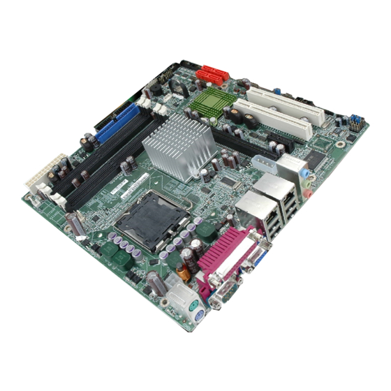
IEI Technology IMB-9454G-R40 User Manual (165 pages)
Micro ATX Motherboard with Intel Core 2 Duo/Pentium 4/ Pentium D/Celeron D CPU with a 533/800/1066 MHz FSB, VGA, Dual PCIe GbE, SATA 3Gb/s, USB 2.0, Audio and COM
Brand:
IEI Technology
| Category:
Motherboard
| Size: 7.36 MB
Table of Contents
User Manual
1
Table of Contents
4
1 Introduction
15
Imb-9454G Overview
16
IMB-9454G Applications
16
IMB-9454G Benefits
16
IMB-9454G Features
17
Figure 1-1: IMB-9454G Board Overview (Top View)
17
Imb-9454G Board Overview
17
IMB-9454G Connectors
18
Technical Specifications
19
Table 1-1: Technical Specifications
20
2 Detailed Specifications
21
Dimensions
22
Board Dimensions
22
Figure 2-1: IMB-9454G Dimensions (MM)
22
Overview
22
Cpu Support
23
Intel ® Core™2 Duo
23
Table-2-1: Supported Cpus
23
External Interface Panel Dimensions
23
Figure 2-2: External Interface Panel Dimensions (MM)
23
Table 2-2: Power Consumption
31
Optional Accessory Items
32
Intel ® Celeron ® D
24
Intel ® Pentium ® 4
24
Intel ® Pentium ® D
24
On-Board Chipsets
25
Northbridge and Southbridge Chipsets
25
Intel 945G Northbridge Chipset
25
Intel ICH7 Southbridge Chipset
26
Graphics Support
26
Gbe Ethernet
27
Memory Support
27
Pci Bus Interface Support
27
Drive Interfaces
28
SATA Drives
28
IDE Interfaces
28
Floppy Disk Drive (FDD)
28
Serial Ports
28
Bios
29
Infrared Data Association (Irda) Interface
29
Operating Temperature and Temperature Control
29
Real Time Clock
29
Usb Interfaces
29
Audio Codec
30
Packaged Contents and Optional Accessory Items
31
Package Contents
31
Power Consumption
31
3 Connectors and Jumpers
33
Figure 3-1: Connector and Jumper Locations
34
Table 3-1: Peripheral Interface Connectors
36
On-Board Jumpers
37
Rear Panel Connectors
37
Peripheral Interface Connectors
34
IMB-9454G Layout
34
Peripheral Interface Connectors
35
Table 3-3: On-Board Jumpers
37
Figure 3-2: Audio Connector Location
38
Audio CD-In Connector
39
Table 3-2: Rear Panel Connectors
37
Internal Peripheral Connectors
38
Audio Connector
38
Table 3-4: Audio Connector Pinouts
39
Table 3-5: Audio CD-In Connector Pinouts
39
Table 3-6: Audio AUX-In Connector Pinouts
40
Figure 3-4: Audio AUX-In Connector Location
40
Fan Connectors
41
Figure 3-3: Audio CD-In Connector Location
39
Audio AUX-In Connector
40
CPU 12V Power Connector
40
Table 3-7: CPU 12V Power Connector Pinouts
41
Figure 3-6: Fan Connector Locations
42
Table 3-8: CPU Fan Connector Pinouts
42
Table 3-9: System Fan Connector Pinouts
42
Figure 3-7: FDD Connector Connector Location
43
Figure 3-8: Front Panel Audio Connector Location
44
Table 3-10: FDD Connector Pinouts
44
Front Panel Connector
45
Table 3-11: Front Panel Audio Connector Pinouts
45
Figure 3-9: Front Panel Connector Location
46
GPIO Connector
46
Table 3-12: Front Panel Connector Pinouts
46
Figure 3-10: GPIO Connector Location
47
HD Audio Connector
47
Table 3-13: GPIO Connector Pinouts
47
Figure 3-11: HD Audio Connector Location
48
IDE Connector
48
Front Panel Audio Connector
44
Table 3-14: HD Audio Connector Pinouts
48
Figure 3-12: IDE Device Connector Location
49
Table 3-15: IDE Connector Pinouts
50
Figure 3-14: PCI Express X1 Slot Locations
51
PCI Express X1 Slot
51
Table 3-16: IR Connector Pinouts
51
PCI Express X16 Slot
52
Table 3-17: PCI Express X1 Slot Pinouts
52
Figure 3-15: PCI Express X16 Slot Location
53
PCI Express Power Connector
54
Table 3-18: Pcie X16 Side a Pinouts
54
Table 3-19: Pcie X16 Side B Pinouts
54
Figure 3-16: Pcie X16 Power Connector Location
55
Power Connector
55
Figure 3-13: IR Connector Location
50
IR Interface Connector
50
Table 3-20: Pcie X16 Power Connector Pinouts
55
Table 3-22: RS-422/485 Connector Pinouts
57
Figure 3-19: Serial Port Connector Locations
58
Table 3-23: COM2 COM3, COM4, COM5 and COM6 Pinouts
58
Figure 3-20: SATA Drive Connector Locations
59
SATA Drive Connectors
59
Table 3-24: SATA Drive Connector Pinouts
59
Figure 3-21: SPDIF Connector Locations
60
SPDIF Connector
60
Table 3-25: SPDIF Pinouts
60
Figure 3-22: SPI Flash Connector Location
61
SPI Flash Connector
61
Table 3-26: SPI Flash Connector Pinouts
61
Figure 3-23: TPM Connector Location
62
TPM Connector
62
Figure 3-24: Internal USB Connector Locations
63
Internal USB Connectors
63
Table 3-27: TPM Connector Pinouts
63
Table 3-28: USB3 and USB4 Pinouts
63
Audio Connectors
64
External Interface Connectors
64
Figure 3-25: IMB-9454G External Interface Connectors
64
CRT Connector
65
Figure 3-26: Audio Connector
65
Figure 3-27: VGA Connector
65
Ethernet Connectors
66
Table 3-29: VGA Connector Pinouts
66
Table 3-30: LAN1 and LAN2 Pinouts
66
Figure 3-28: RJ-45 Ethernet Connector
67
Keyboard/Mouse Connector
67
Table 3-31: RJ-45 Ethernet Connector Leds
67
Figure 3-29: PS/2 Pinouts
68
Serial Port Connectors
68
Table 3-32: PS/2 Connector Pinouts
68
Figure 3-30: External Serial Port Connector
69
Parallel Port Connector
69
Table 3-33: External Serial Port Pinouts
69
USB Connector
70
Table 3-21: Power Connector Pinouts
56
Figure 3-17: Power Connector Location
56
Figure 3-18: RS-422/485 Connector Location
57
RS-422/485 Connector
57
Serial Port Connectors
57
Figure 3-5: CPU 12V Power Connector Location
41
FDD Connector
43
Figure 3-31 Parallel Port Connector Pinout Locations
70
Table 3-34: Parallel Port Connector Pinouts
70
Table 3-35: External USB Connector Pinouts
71
4 Installation and Configuration
72
Anti-Static Precautions
73
Installation Considerations
73
Installation Notices
73
Unpacking
74
Unpacking Precautions
74
Checklist
75
Imb-9454G Motherboard Installation
75
Socket Lga775 Cpu Installation
76
CPU Selection: HT Functionality Requirements
76
CPU Installation
76
Figure 4-1: Intel LGA775 Socket
77
Figure 4-3: Open the CPU Socket Load Plate
78
Figure 4-4: Insert the Socket LGA775 CPU
79
Figure 4-5: IEI LGA-775 Cooling Kit
80
Figure 4-7: Installing the DIMM Module
83
Figure 4-8: Locking the DIMM Module
83
Figure 4-9: Connection of IDE Connector
84
Table 4-1: IEI Provided Cables
84
COM Port Connectors
85
Floppy Drive Connector
85
Figure 4-10 Jumper
86
On-Board Jumpers
86
Table 4-2: On-Board Jumpers
86
Clear CMOS Jumper
87
Figure 4-11: Jumper Locations
87
Chassis Installation
88
COM2 Mode Selection
88
Table 4-3: Clear CMOS Jumper Settings
88
Table 4-4: JP4 Jumper Settings
88
Audio Interface
89
Ethernet Connection
89
Keyboard and Mouse Connection
89
LCD Panel Connection
89
Rear Panel Connectors
89
Serial Connection
89
USB Connection
89
Figure 4-2: Remove the CPU Socket Protective Shield
78
Socket LGA775 Cooling Kit (CF-520) Installation
79
IDE Disk Drive Connector (IDE1)
84
Figure 4-6: Securing the Heat Sink to the PCB Board
81
DIMM Module Installation
82
Purchasing the Memory Module
82
Peripheral Device Connection
83
5 Ami Bios Setup
90
Introduction
91
Starting Setup
91
Using Setup
91
Getting Help
92
Unable to Reboot after Configuration Changes
92
BIOS Menu Bar
92
Main
92
Table 5-1: BIOS Navigation Keys
92
BIOS Menu 1: Main
93
Advanced
94
CPU Configuration
95
IDE Configuration
96
BIOS Menu 4: IDE Configuration
97
IDE Master, IDE Slave
98
BIOS Menu 5: IDE Master and IDE Slave Configuration
99
Floppy Configuration
102
Super IO Configuration
103
BIOS Menu 7: Super IO Configuration
104
Hardware Health Configuration
109
ACPI Configuration
111
General ACPI Configuration
112
APM Configuration
113
BIOS Menu 11: APM Configuration
114
MPS Configuration
116
USB Configuration
117
BIOS Menu 13: USB Configuration
118
USB Mass Storage Device Configuration
120
Boot
120
Boot Settings Configuration
121
BIOS Menu 16: Boot Settings Configuration
122
Boot Device Priority
124
Hard Disk Drives
125
Removable Drives
125
CD/DVD Drives
126
Security
127
Chipset
128
BIOS Menu 20: Chipset
129
North Bridge Configuration
130
Exit
132
6 Software Drivers
134
Available Software Drivers
135
Chipset Driver Installation
135
Figure 6-2: Welcome Screen
136
Figure 6-1: Installshield Wizard Preparation Screen
136
Figure 6-4: Readme Information
137
Figure 6-3: License Agreement
137
Figure 6-5: Restart the Computer
138
Vga Driver
138
Figure 6-6: Starting Install Shield Wizard Screen
139
Figure 6-12: Access Windows Control Panel
142
Figure 6-13: Double Click the System Icon
143
Figure 6-18: Location Browsing Window
147
Figure 6-19: Installshield Wizard Extracting Files
148
Figure 6-20: Audio Driver Install Shield Wizard Starting
148
Figure 6-21: Audio Driver Setup Preparation
149
Figure 6-22: Audio Driver Digital Signal
149
Intel Matrix Storage Manager Installation
150
Figure 6-7: Preparing Setup Screen
139
Figure 6-15: Device Manager List
144
Figure 6-14: Double Click the Device Manager Tab
144
Figure 6-16: Search for Suitable Driver
145
Figure 6-17: Locate Driver Files
146
Realtek Audio Driver (ALC655) Installation
147
Figure 6-8: VGA Driver Installation Welcome Screen
140
Figure 6-9: VGA Driver License Agreement
140
Figure 6-10: VGA Driver Installing Notice
141
Figure 6-11: VGA Driver Installation Complete
141
Realtek LAN Driver (for Gbe LAN) Installation
142
Figure 6-23: Audio Driver Installation Continues
150
Figure 6-24: Audio Driver Installation Complete
150
Figure 6-25: Preparing Setup Screen
151
Abios Configuration Options
153
Bios Configuration Options
153
O Ptions
154
Bwatchdog Timer
157
Cexternal Ac'97 Audio Codec
160
Introduction
161
Accessing the AC'97 CODEC
161
Driver Installation
161
Sound Effect Configuration
162
Accessing the Sound Effects Manager
162
Sound Effect Manager Configuration Options
163
Advertisement
Advertisement
Related Products
IEI Technology IMB-9452
IEI Technology IMB-9454G-R20
IEI Technology IMBA-Q670
IEI Technology IMBA-XQ354
IEI Technology IMBA-8650
IEI Technology IMBA-9654
IEI Technology IMB-X63 Series
IEI Technology IMBA-BDE-1518-R10
IEI Technology IMBA-Q370
IEI Technology IMBA-KX
IEI Technology Categories
Motherboard
Touch Panel
Computer Hardware
Single board computers
Desktop
More IEI Technology Manuals
Login
Sign In
OR
Sign in with Facebook
Sign in with Google
Upload manual
Upload from disk
Upload from URL