Sign In
Upload
Manuals
Brands
IEI Technology Manuals
Motherboard
IMBA-XQ354
IEI Technology IMBA-XQ354 ATX Motherboard Manuals
Manuals and User Guides for IEI Technology IMBA-XQ354 ATX Motherboard. We have
2
IEI Technology IMBA-XQ354 ATX Motherboard manuals available for free PDF download: User Manual
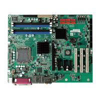
IEI Technology IMBA-XQ354 User Manual (245 pages)
ATX Motherboard for Intel Core 2 Duo/Quad GbE, Intel AMT 3.0, PCIex16, VGA, SATA with RAID 0,1,5,10 PCI, PCIe X4, HD Audio, RoHS Compliant
Brand:
IEI Technology
| Category:
Motherboard
| Size: 9.04 MB
Table of Contents
User Manual
1
Packing List
6
Table of Contents
7
1 Introduction
21
Imba-Xq354 Motherboard Overview
22
Figure 1-1: IMBA-XQ354
22
Benefits
23
Features
23
Imba-Xq354 Overview
24
Connectors
24
Figure 1-2: Overview
24
Technical Specifications
26
Table 1-1: Technical Specifications
27
2 Detailed Specifications
28
Overview
29
Dimensions
29
Board Dimensions
29
Figure 2-1: IMBA-XQ354 Dimensions (MM)
29
External Interface Panel Dimensions
30
Figure 2-2: External Interface Panel Dimensions (MM)
30
Data Flow
31
Compatible Processors
31
Figure 2-3: Data Flow Block Diagram
31
Intel® Q35 Northbridge Chipset
32
Front Side Bus
33
Figure 2-4: Northbridge Connections
33
Memory Controller
34
Pcie X16 Interface
34
Graphics and Display Features
34
VGA Display Capabilities
35
Direct Media Interface (DMI)
35
Intel® ICH9DO Southbridge Chipset
35
Figure 2-5: Southbridge Connections
36
Gigabit Ethernet Controllers
37
Intel® 82566DM Gigabit Ethernet Device
38
Intel® 82573L Gigabit Ethernet Controller
38
High Definition Audio Implementation
37
Low Pin Count (LPC) Interface
39
PCI Interface
39
Pcie Bus
39
Real Time Clock
40
SATA Controller
40
Serial Peripheral Interface (SPI) BIOS
40
USB Controller
40
Lpc Bus Components
40
Ite IT8718F Super I/O Chipset
41
Figure 2-6: Ite IT8718F Super I/O
41
16C550 Uarts
42
Digital Input/Output
42
LPC Interface
42
Enhanced Hardware Monitor
43
Fan Speed Controller
43
Floppy Disk Controller
43
Keyboard/Mouse Controller
43
Parallel Port
44
Fintek F81216DG Serial Port Chip
44
Environmental and Power Specifications
44
System Monitoring
44
Power Consumption
45
Table 2-1: Power Consumption
45
3 Packing List
46
Anti-Static Precautions
47
Unpacking
47
Unpacking Precautions
47
Unpacking Checklist
48
Package Contents
48
Optional Items
49
Table 3-1: Packing List
49
Table 3-2: Optional Items
50
4 Connector Pinouts
51
Peripheral Interface Connectors
52
IMBA-XQ354 Layout
52
Figure 4-1: Connector and Jumper Locations
52
Peripheral Interface Connectors
53
External Interface Panel Connectors
54
Table 4-1: Peripheral Interface Connectors
54
Table 4-2: Rear Panel Connectors
54
Internal Peripheral Connectors
55
ATX CPU Power Connector
55
Figure 4-2: at Power Connector Location
55
Table 4-3: ATX Power Connector Pinouts
55
ATX Power Connector
56
Figure 4-3: ATX Power Connector Pinout Locations
56
Audio Connector
57
Figure 4-4: Audio Connector Pinouts
57
Table 4-4: ATX Power Connector Pinouts
57
CD in Connector
58
Figure 4-5: Audio CD in Connector Location
58
Table 4-5: Audio Connector Pinouts
58
Digital I/O Connector
59
Figure 4-6: Digital I/O Connector Locations
59
Table 4-6: Audio CD in Connector Pinouts
59
CPU Fan Connector
60
Figure 4-7: CPU Fan Connector Location
60
Table 4-7: Digital I/O Connector Pinouts
60
System Fan Connectors
61
Figure 4-8: System Fan Connector Location
61
Table 4-8: CPU Fan Connector Pinouts
61
Floppy Disk Connector
62
Figure 4-9: 34-Pin FDD Connector Location
62
Table 4-9: System Fan Connector Pinouts
62
Front Panel Connector
63
Table 4-10: 34-Pin FDD Connector Pinouts
63
Infrared Interface Connector (5-Pin)
64
Figure 4-10: Front Panel Connector Pinout Locations
64
Table 4-11: Front Panel Connector Pinouts
64
PCI Express X4 Slot
65
Figure 4-11: Infrared Connector Pinout Locations
65
Table 4-12: Infrared Connector Pinouts
65
Figure 4-12: Pcie X4 Connector Locations
66
PCI Express X16 Slot
67
Figure 4-13: Pcie X16 Connector Location
67
Table 4-13: Pcie X4 Pinouts
67
Table 4-14: Pcie X16 Side a Pinouts
68
PCI Slot
69
Table 4-15: Pcie X16 Side B Pinouts
69
Figure 4-14: PCI Slot Location
70
SATA Drive Connectors
72
Table 4-16: PCI Slot
72
SPDIF Connector
73
Figure 4-15: SATA Drive Connector Locations
73
Table 4-17: SATA Drive Connector Pinouts
73
Serial Port Connectors
74
Figure 4-16: SPDIF Connector Pinout Locations
74
Table 4-18: SPDIF Connector Pinouts
74
SPI Flash Connector
75
Figure 4-17: Serial Port Connectors Pinout Locations
75
Table 4-19: Serial Port Connector Pinouts
75
Trusted Platform Module (TPM) Connector
76
Figure 4-18: SPI Flash Connector Pinouts
76
Table 4-20: SPI Flash Connector
76
USB Connectors
77
Figure 4-19: TPM Connector Pinout Locations
77
Table 4-21: TPM Connector Pinouts
77
External Interface Connectors
78
Figure 4-20: USB Connector Pinout Locations
78
Table 4-22: USB Port Connector Pinouts
78
Audio Connector
79
Figure 4-21: IMBA-XQ354 External Interface Connectors
79
Ethernet Connector
80
Figure 4-22: Audio Connector
80
Figure 4-23: Ethernet Connector
80
Table 4-23: Ethernet Connector Pinouts
80
Figure 4-24: PS/2 Connector
81
Keyboard and Mouse Connector
81
Table 4-24: Connector Leds
81
Parallel Port Connector
82
Table 4-25: PS/2 Connectors
82
Figure 4-25: Parallel Port Connector Location
83
Serial Port Connector
83
Table 4-26: Parallel Port Connector Pinouts
83
Table 4-27: Serial Port Pinouts
83
Figure 4-26: Serial Port Pinout Locations
84
Table 4-28: USB Connector Pinouts
84
USB Ports
84
VGA Connector
84
Figure 4-27: VGA Connector
85
Table 4-29: VGA Connector Pinouts
85
5 Installation
86
Anti-Static Precautions
87
Installation Considerations
88
Installation Notices
88
Installation Checklist
89
Cpu, Cpu Cooling Kit and DIMM Installation
90
Socket LGA775 CPU Installation
90
Figure 5-1: Intel LGA775 Socket
91
Figure 5-2: Remove the CPU Socket Protective Shield
91
Figure 5-3: Open the CPU Socket Load Plate
92
Socket LGA775 CF-520 Cooling Kit Installation
93
Figure 5-4: Insert the Socket LGA775 CPU
93
Figure 5-5: Cooling Kit
94
DIMM Installation
95
Figure 5-6: Securing the Heat Sink to the PCB Board
95
Figure 5-7: Installing a DIMM
96
Jumper Settings
97
Table 5-1: Jumpers
97
Clear CMOS Jumper
98
Table 5-2: Clear CMOS Jumper Settings
98
COM Port Pin 9 Function Select
99
Figure 5-8: Clear CMOS Jumper
99
COM Port Pin 9 Voltage Setting Select
100
Figure 5-9: COM Port Pin 9 Function Select Jumper Location
100
Table 5-3: COM Port Pin 9 Function Select Jumper Settings
100
Figure 5-10: COM Port Pin 9 Voltage Setting Select Jumper Location
101
SPDIF out Selection
101
Table 5-4: COM Port Pin 9 Voltage Setting Select Jumper Settings
101
Figure 5-11: SPDIF out Selection Jumper Pinout Location
102
Table 5-5: SPDIF out Selection Jumper Settings
102
Chassis Installation
103
Airflow
103
IMBA-XQ354 Installation
103
Dual RS-232 Cable with Slot Bracket
103
Single RS-232 Cable with Slot Bracket
104
Figure 5-12: Dual RS-232 Cable Installation
104
SATA Drive Connection
105
Figure 5-13: Single RS-232 Cable Installation
105
Figure 5-14: SATA Drive Cable Connection
106
USB Cable (Dual Port) with Slot Bracket
107
Figure 5-15: SATA Power Drive Connection
107
USB Cable (Four Port)
108
Figure 5-16: Dual USB Cable Connection
108
Figure 5-17: Four Port USB Cable Connection
109
External Peripheral Interface Connection
110
Keyboard and Mouse
110
Lan
111
Figure 5-18: PS/2 Keyboard/Mouse Connector
111
Parallel Device Connection
112
Figure 5-19: LAN Connection
112
Serial Device
113
Figure 5-20: Parallel Device Connector
113
Usb
114
Figure 5-21: Serial Device Connector
114
VGA Monitor
115
Figure 5-22: USB Connector
115
Audio Connector
116
Figure 5-23: VGA Connector
116
Figure 5-24: Audio Connector
117
6 Bios Setup
118
Introduction
119
Starting Setup
119
Using Setup
119
Getting Help
120
Unable to Reboot after Configuration Changes
120
BIOS Menu Bar
120
Table 6-1: BIOS Navigation Keys
120
Main
121
Advanced
122
CPU Configuration
124
IDE Configuration
125
IDE Master, IDE Slave
127
Floppy Configuration
132
Super IO Configuration
133
Hardware Health Configuration
136
APM Configuration
140
ACPI Configuration
142
AHCI Configuration
143
Intel AMT Configuration
144
ME Subsystem Configuration
145
Remote Access Configuration
146
Trusted Computing
150
USB Configuration
151
Pci/Pnp
152
Boot
155
Boot Settings Configuration
156
Boot Device Priority
158
Hard Disk Drives
159
CD/DVD Drives
160
Removable Drives
161
Security
162
Chipsets
163
Northbridge Chipset Configuration
164
Southbridge Chipset Configuration
166
Exit
167
7 Software Drivers
169
Available Software Drivers
170
Starting the Driver Program
170
Figure 7-1: Start up Screen
171
Figure 7-2: Drivers
171
Chipset Driver
172
Figure 7-3: Intel® Chipset Driver Directory
172
Figure 7-4: Intel® Setup Welcome Screen
172
Figure 7-5: Intel® Chipset Driver License Agreement
173
Figure 7-6: Readme File
173
Graphics Driver
174
Figure 7-7: Intel® Chipset Driver Complete Installation Screen
174
Figure 7-8: Graphics Driver File
175
Figure 7-9: Graphics Driver Readme File
175
Figure 7-10: Graphics Driver Installation Welcome Screen
176
Figure 7-11: GMA Driver License Agreement
176
Figure 7-12: GMA Driver Installing Notice
177
Figure 7-13: GMA Driver Installation Complete
177
Lan Driver
178
Figure 7-14: GMA Driver Installing Notice
178
Figure 7-15: LAN Driver File
179
Figure 7-16: LAN Driver Welcome Screen
179
Figure 7-17: LAN Driver License Agreement
180
Figure 7-18: LAN Driver Setup Options
180
Figure 7-19: LAN Driver Installation Ready Window
181
Audio Driver
182
BIOS Setup
182
Figure 7-20: LAN Driver Installation Progress
182
Driver Installation
183
Figure 7-21: Audio Setup File
183
Figure 7-22: Installshield Wizard Welcome Screen
183
Intel ® Matrix Storage Manager Driver
184
Figure 7-23: Installation Wizard Finished
184
Figure 7-24: SATA RAID Driver Installation Program
185
Figure 7-25: SATA RAID Setup Program Icon
186
Figure 7-26: Installshield Wizard Setup Screen
186
Figure 7-27: Matrix Storage Manager Setup Screen
187
Figure 7-28: Matrix Storage Manager Welcome Screen
187
Figure 7-29: Matrix Storage Manager Warning Screen
188
Figure 7-30: Matrix Storage Manager License Agreement
188
Figure 7-31: Matrix Storage Manager Readme File
189
Intel® AMT (HECI) Driver
190
Figure 7-32: Matrix Storage Manager Setup Complete
190
Figure 7-33: AMT HECI Driver Directory
191
Figure 7-34: AMT HECI Welcome Screen
191
Figure 7-35: AMT HECI License Agreement
192
Figure 7-36: AMT HECI Driver Readme File
192
Intel® AMT (SOL) Driver
193
Figure 7-37: AMT HECI Driver Installation Complete
193
Figure 7-38: IAMT Driver Directory
194
Figure 7-39: IAMT Welcome Screen
194
Figure 7-40: IAMT License Agreement
195
Figure 7-41: IAMT Readme File
195
Figure 7-42: Completed Installation
196
8 Intel® Amt Setup
197
Intel ® Amt Setup Procedure
198
Intel ® Management Engine Bios Extension
198
Figure 8-1: Intel® Active Management Technology Status Dialog
198
Figure 8-2: Intel® Current ME Password
199
Figure 8-3: Change Intel® ME Password
200
Figure 8-4: Verify New Password
200
Figure 8-5: Intel® AMT Configuration
200
Figure 8-6: Provision Model
201
Figure 8-7: Intel® AMT 3.0 Mode
201
Figure 8-8: Enterprise
202
Figure 8-9: Enable Network Interface
202
Using the Intel AMT Web Interface
203
Figure 8-10: Exit
203
Figure 8-11: Intel® AMT Web Address
204
Figure 8-12: Intel® AMT Web Login Dialog
205
Figure 8-13: Intel® AMT Web Interface
206
ABIOS Options
207
B Terminology
211
C Digital I/O Interface
215
Introduction
216
Dio Connector Pinouts
216
Assembly Language Samples
216
Enable the DIO Input Function
216
Enable the DIO Output Function
217
D Watchdog Timer
218
E Address Mapping
221
Direct Memory Access (Dma)
222
A Ccess (Dma)
222
Input/Output (IO)
223
Interrupt Request (Irq)
225
Equest (Irq)
225
Memory
226
F Compatibility
227
Compatible Operating Systems
228
Compatible Processors
228
Compatible Memory Modules
229
G Hazardous Materials Disclosure
231
Hazardous Materials Disclosure Table for IPB Products Certified as Rohs Compliant under 2002/95/EC Without Mercury
232
HAC'97 Audio Codec
235
Introduction
236
Accessing the AC'97 CODEC
236
Driver Installation
236
Sound Effect Configuration
237
Accessing the Sound Effects Manager
237
Advertisement
IEI Technology IMBA-XQ354 User Manual (244 pages)
ATX motherboard for Intel Care 2 Dua/Quad GbE, Intel AMT 3.0, PCIe x16, VGA, SATA with RAID 0,1,5,10 PCI, PCIe x4, HD Audio, RoHS Compliant
Brand:
IEI Technology
| Category:
Motherboard
| Size: 8.57 MB
Table of Contents
Table of Contents
7
User Manual
1
Packing List
6
Table of Contents
7
List of Figures
14
Bios Menus
20
Introduction
21
Imba-Xq354 Motherboard Overview
22
Benefits
23
Features
23
Imba-Xq354 Overview
24
Connectors
24
Figure 1-2: Overview
24
Technical Specifications
26
Table 1-1: Technical Specifications
27
Detailed Specifications
28
Overview
29
Dimensions
29
Board Dimensions
29
Figure 2-1: IMBA-XQ354 Dimensions (MM)
29
External Interface Panel Dimensions
30
F Igure 2-2: External Interface Panel Dimensions
30
Data Flow
31
Compatible Processors
31
Figure 2-3: Data Flow Block Diagram
31
Intel® Q35 Northbridge Chipset
32
Figure 2-4: Northbridge Connections
33
Front Side Bus
33
Graphics and Display Features
34
Memory Controller
34
Pcie X16 Interface
34
Direct Media Interface (DMI)
35
VGA Display Capabilities
35
Intel® ICH9DO Southbridge Chipset
35
Figure 2-5: Southbridge Connections
36
Gigabit Ethernet Controllers
37
High Definition Audio Implementation
37
Intel® 82566DM Gigabit Ethernet Device
38
Intel® 82573L Gigabit Ethernet Controller
38
Low Pin Count (LPC) Interface
39
PCI Interface
39
Pcie Bus
39
Real Time Clock
40
F Igure 2-6: Ite IT8718F Super I
41
C550 Uarts
42
Digital Input/Output
42
Lpc Interface
42
Enhanced Hardware Monitor
43
Fan Speed Controller
43
Floppy Disk Controller
43
Keyboard/Mouse Controller
43
Fintek F81216Dg Serial Port Chip
44
Parallel Port
44
System Monitoring
44
Table 2-1: Power Consumption
45
Unpacking Checklist
48
Optional Items
49
Table 3-1: Packing List
49
Table 3-2: Optional Items
50
Connector Pinouts
51
Figure 4-1: Connector and Jumper Locations
52
Imba-Xq354 Layout
52
T Able 4-1: Peripheral Interface Connectors
52
Atx Cpu Power Connector
54
External Interface Panel Connectors
54
Table 4-2: Rear Panel Connectors
54
Figure 4-2: at Power Connector Location
55
Table 4-3: ATX Power Connector Pinouts
55
Figure 4-3: ATX Power Connector Pinout Locations
56
Table 4-4: ATX Power Connector Pinouts
56
Figure 4-4: Audio Connector Pinouts
57
Table 4-5: Audio Connector Pinouts
57
CD in Connector
57
Figure 4-5: Audio CD in Connector Location
58
Table 4-6: Audio CD in Connector Pinouts
58
Digital I/O Connector
58
Figure 4-6: Digital I/O Connector Locations
59
Table 4-7: Digital I/O Connector Pinouts
59
Cpu Fan Connector
59
Figure 4-7: CPU Fan Connector Location
60
Table 4-8: CPU Fan Connector Pinouts
60
System Fan Connectors
60
Figure 4-8: System Fan Connector Location
61
Table 4-9: System Fan Connector Pinouts
61
Floppy Disk Connector
61
Figure 4-9: 34-Pin FDD Connector Location
62
Figure 4-10: Front Panel Connector Pinout Locations
63
Table 4-10: 34-Pin FDD Connector Pinouts
63
Figure 4-11: Infrared Connector Pinout Locations
64
Table 4-11: Front Panel Connector Pinouts
64
Infrared Interface Connector (5-Pin)
64
Figure 4-12: Pcie X4 Connector Locations
65
Table 4-12: Infrared Connector Pinouts
65
Pci Express X4 Slot
65
Table 4-13: Pcie X4 Pinouts
66
Pci Express X16 Slot
66
F Igure 1-1: IMBA-XQ354
67
Figure 4-13: Pcie X16 Connector Location
67
Table 4-14: Pcie X16 Side a Pinouts
68
Table 4-15: Pcie X16 Side B Pinouts
68
T Able 4-16: PCI Slot
68
Figure 4-14: PCI Slot Location
69
Sata Drive Connectors
71
Figure 4-15: SATA Drive Connector Locations
72
Table 4-17: SATA Drive Connector Pinouts
72
Spdif Connector
72
Figure 4-16: SPDIF Connector Pinout Locations
73
Table 4-18: SPDIF Connector Pinouts
73
Serial Port Connectors
73
Figure 4-17: Serial Port Connectors Pinout Locations
74
Table 4-19: Serial Port Connector Pinouts
74
T Able 4-20: SPI Flash Connector
74
Figure 4-18: SPI Flash Connector Pinouts
75
Trusted Platform Module (Tpm) Connector
75
Figure 4-19: TPM Connector Pinout Locations
76
Table 4-21: TPM Connector Pinouts
76
Usb Connectors
76
Figure 4-20: USB Connector Pinout Locations
77
Table 4-22: USB Port Connector Pinouts
77
Figure 4-21: IMBA-XQ354 External Interface Connectors
78
Figure 4-23: Ethernet Connector
79
Table 4-23: Ethernet Connector Pinouts
79
Figure 4-24: PS/2 Connector
80
Table 4-24: Connector Leds
80
Keyboard and Mouse Connector
80
Table 4-25: PS/2 Connectors
81
Parallel Port Connector
81
Figure 4-25: Parallel Port Connector Location
82
Table 4-26: Parallel Port Connector Pinouts
82
Table 4-27: Serial Port Pinouts
82
Serial Port Connector
82
Figure 4-26: Serial Port Pinout Locations
83
Table 4-28: USB Connector Pinouts
83
Usb Ports
83
Vga Connector
83
Figure 4-27: VGA Connector
84
Table 4-29: VGA Connector Pinouts
84
Installation Notices
87
Installation Checklist
88
Socket Lga775 Cpu Installation
89
Figure 5-1: Intel LGA775 Socket
90
Figure 5-2: Remove the CPU Socket Protective Shield
90
Figure 5-3: Open the CPU Socket Load Plate
91
Figure 5-4: Insert the Socket LGA775 CPU
92
Socket Lga775 Cf-520 Cooling Kit Installation
92
Figure 5-5: Cooling Kit
93
Figure 5-6: Securing the Heat Sink to the PCB Board
94
DIMM Installation
94
Figure 5-7: Installing a DIMM
95
Table 5-1: Jumpers
96
Jumper Settings
96
Table 5-2: Clear CMOS Jumper Settings
97
Figure 5-8: Clear CMOS Jumper
98
Com Port Pin 9 Function Select
98
Figure 5-9: COM Port Pin 9 Function Select Jumper Location
99
Table 5-3: COM Port Pin 9 Function Select Jumper Settings
99
Com Port Pin 9 Voltage Setting Select
99
Figure 5-10: COM Port Pin 9 Voltage Setting Select Jumper Location
100
Table 5-4: COM Port Pin 9 Voltage Setting Select Jumper Settings
100
Spdif out Selection
100
Figure 5-11: SPDIF out Selection Jumper Pinout Location
101
Table 5-5: SPDIF out Selection Jumper Settings
101
Imba-Xq354 Installation
102
Dual Rs-232 Cable with Slot Bracket
102
Figure 5-12: Dual RS-232 Cable Installation
103
Single Rs-232 Cable with Slot Bracket
103
Figure 5-13: Single RS-232 Cable Installation
104
Sata Drive Connection
104
Figure 5-14: SATA Drive Cable Connection
105
Figure 5-15: SATA Power Drive Connection
106
Usb Cable (Dual Port) with Slot Bracket
106
Figure 5-16: Dual USB Cable Connection
107
Usb Cable (Four Port)
107
Figure 5-17: Four Port USB Cable Connection
108
Keyboard and Mouse
109
Figure 5-18: PS/2 Keyboard/Mouse Connector
110
Figure 5-19: LAN Connection
111
Parallel Device Connection
111
Figure 5-20: Parallel Device Connector
112
Serial Device
112
Figure 5-21: Serial Device Connector
113
Figure 5-22: USB Connector
114
Vga Monitor
114
Figure 5-23: VGA Connector
115
Figure 5-24: Audio Connector
116
Bios Setup
117
Starting Setup
118
Using Setup
118
Table 6-1: BIOS Navigation Keys
119
Getting Help
119
Unable to Reboot after Configuration Changes
119
Bios Menu Bar
119
BIOS Menu 1: Main
120
BIOS Menu 2: Advanced
122
BIOS Menu 3: CPU Configuration
123
BIOS Menu 4: IDE Configuration
124
BIOS Menu 5: IDE Master and IDE Slave Configuration
126
BIOS Menu 6: IDE Master and IDE Slave Configuration
131
Floppy Configuration
131
BIOS Menu 7: Super IO Configuration
132
BIOS Menu 8: Hardware Health Configuration
135
BIOS Menu 9: Hardware Health Configuration 2
138
Apm Configuration
139
BIOS Menu 10: AHCI Port N Configuration Menu
139
BIOS Menu 11: Advanced ACPI Configuration
141
BIOS Menu 12: AHCI Configuration
142
BIOS Menu 13: Intel AMT Configuration
143
BIOS Menu 14: ME Subsystem Configuration
144
Remote Access Configuration
145
BIOS Menu 15: Remote Access Configuration [Advanced]
146
BIOS Menu 16: Trusted Computing
149
BIOS Menu 17: USB Configuration
150
BIOS Menu 18: Pci/Pnp Configuration
152
BIOS Menu 19: Boot
154
BIOS Menu 20: Boot Settings Configuration
155
BIOS Menu 21: Boot Device Priority Settings
157
BIOS Menu 22: Hard Disk Drives
158
BIOS Menu 23: CD/DVD Drives
159
BIOS Menu 24: Removable Drives
160
BIOS Menu 25: Security
161
BIOS Menu 26: Chipset
162
BIOS Menu 27:Northbridge Chipset Configuration
163
BIOS Menu 28:Southbridge Chipset Configuration
165
BIOS Menu 29:Exit
166
Software Drivers
168
Figure 7-1: Start up Screen
170
Figure 7-2: Drivers
170
Figure 7-3: Intel® Chipset Driver Directory
171
Figure 7-4: Intel® Setup Welcome Screen
171
Figure 7-5: Intel® Chipset Driver License Agreement
172
Figure 7-6: Readme File
172
Figure 7-7: Intel® Chipset Driver Complete Installation Screen
173
Graphics Driver
173
Figure 7-8: Graphics Driver File
174
Figure 7-9: Graphics Driver Readme File
174
Figure 7-10: Graphics Driver Installation Welcome Screen
175
Figure 7-11: GMA Driver License Agreement
175
Figure 7-12: GMA Driver Installing Notice
176
Figure 7-13: GMA Driver Installation Complete
176
Figure 7-14: GMA Driver Installing Notice
177
Lan Driver
177
Figure 7-15: LAN Driver File
178
Figure 7-16: LAN Driver Welcome Screen
178
Figure 7-17: LAN Driver License Agreement
179
Figure 7-18: LAN Driver Setup Options
179
Figure 7-19: LAN Driver Installation Ready Window
180
Figure 7-20: LAN Driver Installation Progress
181
Audio Driver
181
Figure 7-21: Audio Setup File
182
Figure 7-22: Installshield Wizard Welcome Screen
182
Driver Installation
182
Figure 7-23: Installation Wizard Finished
183
Intel Matrix Storage Manager Driver
183
Figure 7-24: SATA RAID Driver Installation Program
184
Figure 7-25: SATA RAID Setup Program Icon
185
Figure 7-26: Installshield Wizard Setup Screen
185
Figure 7-27: Matrix Storage Manager Setup Screen
186
Figure 7-28: Matrix Storage Manager Welcome Screen
186
Figure 7-29: Matrix Storage Manager Warning Screen
187
Figure 7-30: Matrix Storage Manager License Agreement
187
Figure 7-31: Matrix Storage Manager Readme File
188
Figure 7-32: Matrix Storage Manager Setup Complete
189
Figure 7-33: AMT HECI Driver Directory
190
Figure 7-34: AMT HECI Welcome Screen
190
Figure 7-35: AMT HECI License Agreement
191
Figure 7-36: AMT HECI Driver Readme File
191
Figure 7-37: AMT HECI Driver Installation Complete
192
Figure 7-38: IAMT Driver Directory
193
Figure 7-39: IAMT Welcome Screen
193
Figure 7-40: IAMT License Agreement
194
Figure 7-41: IAMT Readme File
194
Figure 7-42: Completed Installation
195
Intel® Amt Setup
196
Figure 8-1: Intel® Active Management Technology Status Dialog
197
Intel Amt Setup Procedure
197
Figure 8-2: Intel® Current ME Password
198
Figure 8-3: Change Intel® ME Password
199
Figure 8-4: Verify New Password
199
Figure 8-5: Intel® AMT Configuration
199
Figure 8-6: Provision Model
200
Figure 8-7: Intel® AMT 3.0 Mode
200
Figure 8-8: Enterprise
201
Figure 8-9: Enable Network Interface
201
Figure 8-11: Intel® AMT Web Address
203
Figure 8-12: Intel® AMT Web Login Dialog
204
Figure 8-13: Intel® AMT Web Interface
205
Bios Options
206
Watchdog Timer
217
Address Mapping
220
Advertisement
Related Products
IEI Technology IMBA-X9654
IEI Technology IMBA-XQ354S
IEI Technology IMBA-Q670
IEI Technology IMBA-C2060
IEI Technology IMBA-Q170-i2
IEI Technology IMBA-9454B-R11
IEI Technology IMBA-Q370
IEI Technology IMB-ADL-H610
IEI Technology IMBA-KX
IEI Technology IMBA-C604EN
IEI Technology Categories
Motherboard
Touch Panel
Computer Hardware
Single board computers
Desktop
More IEI Technology Manuals
Login
Sign In
OR
Sign in with Facebook
Sign in with Google
Upload manual
Upload from disk
Upload from URL