Icom IC-25E Manuals
Manuals and User Guides for Icom IC-25E. We have 6 Icom IC-25E manuals available for free PDF download: Maintenance Manual, Instruction Manual
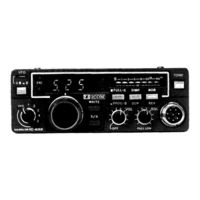
Icom IC-25E Maintenance Manual (77 pages)
144 MHz
Brand: Icom
|
Category: Transceiver
|
Size: 13 MB
Table of Contents
Advertisement

Icom IC-25E Instruction Manual (37 pages)
144MHz FM transceiver
Brand: Icom
|
Category: Transceiver
|
Size: 4 MB
Table of Contents

Icom IC-25E Maintenance Manual (77 pages)
144MHZ FM
Brand: Icom
|
Category: Transceiver
|
Size: 20 MB
Advertisement

Icom IC-25E Instruction Manual (37 pages)
Brand: Icom
|
Category: Transceiver
|
Size: 10 MB
Table of Contents

Icom IC-25E Instruction Manual (40 pages)
144MHz FM Transceiver
Brand: Icom
|
Category: Transceiver
|
Size: 12 MB

Icom IC-25E Instruction Manual (36 pages)
144MHz FM Transceiver
Brand: Icom
|
Category: Transceiver
|
Size: 4 MB
Advertisement