Sign In
Upload
Manuals
Brands
Huber Manuals
Temperature Controller
Pilot ONE
Huber Pilot ONE Manuals
Manuals and User Guides for Huber Pilot ONE. We have
7
Huber Pilot ONE manuals available for free PDF download: Operation Manual, Manual, Technical Bulletin
Huber Pilot ONE Operation Manual (98 pages)
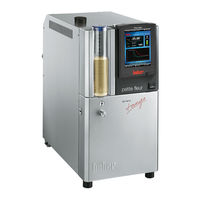
Unistat Pilot ONE
Brand:
Huber
| Category:
Temperature Controller
| Size: 7 MB
Table of Contents
Table of Contents
8
1 Introduction
14
Details on the Declaration of Conformity
14
Safety
14
Symbols Used for Safety Instructions
14
Proper Operation
15
Reasonably Foreseeable Misuse
15
Responsible Bodies and Operators - Obligations and Requirements
16
Obligations of the Responsible Body
16
Proper Disposal of Resources and Consumables
16
Temperature Control Unit with Natural Refrigerants (NR)
17
Requirements for Operators
19
Obligations of the Operators
20
General Information
20
Description of Workstation
20
Safety Devices to DIN 12876
20
Further Protective Devices
21
Power Interruption
21
Alarm Functions
21
Warning Messages
21
Exemplary Illustrations of the Cooling Variants
22
Air Cooling
22
Water Cooling
22
Consequence of Inadequate Energy Dissipation
23
2 Commissioning
24
Commissioning In-Plant Transport
24
Lifting and Transporting the Temperature Control Unit
24
Temperature Control Unit with Lifting Eyes
24
Temperature Control Unit Without Lifting Eyes
25
Positioning the Temperature Control Unit
25
Temperature Control Unit with Casters
25
Temperature Control Unit Without Casters
25
Transportation Lock
25
Transportation Lock Type a
26
Releasing the Transportation Lock (Operating Position)
26
Tightening the Transportation Lock (Transport Position)
26
Transportation Lock Type B
26
Unpacking
27
Ambient Conditions
27
EMC-Specific Notes
28
Installation Conditions
29
Temperature Control Unit for Outdoor Installation Incl. Winter Operation
29
Recommended Temperature Control and Cooling Water Hoses
30
Wrench Sizes and Torques
30
Temperature Control Units with Water Cooling
31
Preparations for Operation
32
Unscrewing/Activating the Leveling Feet (if Any)
32
2.10.2 Opening/Closing Valves
32
Mounting/Removing the Isolating Sleeve (Optional)
33
Mounting the Isolating Sleeve (Only for Externally Open Applications)
33
Removing the Isolating Sleeve (Only for Externally Closed Applications)
33
Connecting an Externally Closed/Open Application
34
2.11.1 Connecting an Externally Closed Application
34
Connecting an Externally Open Application (Bath)
34
Connecting to the Power Supply
35
Connection Using Socket with Protective Earth (PE)
35
2.12.2 Connection Via Hard Wiring
35
2.12.3 Connecting the Functional Earth
36
2.12.4 Converting the Power Supply Connection
36
3 Function Description
37
Function Description of the Temperature Control Unit
37
General Functions
37
Other Functions
37
Information on the Thermal Fluids
38
To be Noted When Planning the Test
39
Pilot ONE®" Controller
40
Functional Overview of "Pilot ONE
40
Unistat® LED Diagram
42
Clock/Event Function
42
Rechargeable Accumulator
42
Programmable Event Function
43
Event Function "Alarm Clock Event
43
Event Function "Program Event
43
Operation Via the Touch Screen
43
Display Instruments
43
The Touchscreen [88]
43
The LED-Indicator Temperature [90]
44
The LED-Indicator Flow Chart [91]
44
The LED-Indicator Status [92]
44
Control Instruments
44
The Touchbuttons
44
The Categories
44
The Sub-Categories
45
The Dialogs
45
Function Examples
45
3.10.1 Display of Software Version
45
3.10.2 Start & Stop
45
3.10.3 Copying the Settings to a Data Carrier
46
Saving to a USB Flash Drive
46
Loading from a USB Flash Drive
46
3.10.4 Restore Factory Settings
47
Restore to Factory Settings Without Overtemperature Protection
48
Restore to Factory Settings Including Overtemperature Protection
48
4 Setup Mode
50
Turning on the Temperature Control Unit
50
Setting the Overtemperature Protection
50
General Information on the Overtemperature Protection
51
Setting "OT Limit: Heating
51
Setting "OT Expansion Vessel
52
Setting "Process Safety
52
Monitoring Via "Display OT Values
52
Testing Overtemperature Protection for Functionality
52
Adjusting the Delta T Limiter
53
Changing the Delta T Limiter
53
The Temperature Control Circuit
53
Select Temperature Control: Internal or Process
54
Temperature Control to Internal Temperature
54
Temperature Control to Process Temperature
54
Delta T Limiter
55
Monitoring the Pt100 Temperature Sensors
55
Optimum Control Parameters for Optimum Temperature Control
55
Sub-Category: "Select Auto/Expert Mode
56
Sub-Category: "Configuration Auto
56
Sub-Category: "Find Parameters
56
Sub-Category: "Control Dynamics
58
Sub-Category: "Fluid Properties
59
Sub-Category: "Display Parameters
60
Category: "Configuration Manual
60
Sub-Category: "Change Parameters
60
Sub-Category: "Display Parameters
61
Sub-Category: "Control Structure
62
4.2.10 Sub-Category: "Reset Parameters
62
Sub-Category: "Display Parameters
62
4.2.12 Setting the Setpoint Thresholds
63
4.2.13 Setting the Setpoint
63
Filling, Venting, Degassing and Draining
64
Externally Closed Application
64
Filling and Venting Externally Closed Application
64
Degassing Externally Closed Applications
66
Draining Externally Closed Applications
68
Externally Open Application
68
Filling and Venting Externally Open Application
69
Degassing Externally Open Applications
70
Draining Externally Open Applications
71
Normal Operation Automatic Operation
73
Starting the Temperature Control Process
73
Temperature Control
73
Ending/Cancelling the Temperature Control Program
74
Starting the Temperature Control Program
74
Temperature Control Via a Created Temperature Control Program
74
10/100 Mbps Ethernet for RJ45 Network Sockets
75
Normal Operation
73
Ending the Temperature Control Process
73
Interfaces and Software Update
75
Interfaces at the "Pilot ONE®" Controller
75
USB-2.0 Interface
75
Interfaces at the "Unistat® Control ONE
76
Interfaces at the "Unistat® Control ONE" Side
76
Jack ECS (External Control Signal) Standby
76
Removing the Cover
76
USB-2.0 Interface, Device
76
USB-2.0 Interface, Host
76
Connector POKO (Floating Contact) Alarm
77
Female RS232 Serial (with Adapter Cable)
78
Interfaces at the "Unistat® Control ONE" Top Side
78
Service Interface
78
Connection Jack for Pt100 Process Controller Sensor
79
Interfaces at the Com.g@Te® (Optional)
79
Connector POKO (Floating Contact) Alarm
80
Jack AIF Reg-E-Prog
80
Jack ECS (External Control Signal) Standby
80
Jack LEVEL (Com.g@Te® External Only)
80
Firmware Update
81
Jack RS232/RS485 Serial
81
7 Service/Maintenance
82
Service/Maintenance Messages from the Temperature Control Unit
82
Replacing the "Pilot ONE®" or "Unistat® Control ONE
82
Replacing the "Pilot ONE
82
Replacing the "Unistat® Control ONE
83
Maintenance
83
Function Check and Visual Inspection
83
Replacing Temperature Control or Coolant Hoses
84
Replacing Temperature Control Hoses
84
Replacing Coolant Hoses
85
Clean Liquefier Fins (Air-Cooled Temperature Control Unit)
85
Clean Hat-Type Strainer (Dirt Trap) (Water-Cooled Temperature Control Unit)
86
Empty the Drip Tray
87
Thermal Fluid Inspection, Replacement and Circuit Cleaning
87
Thermal Fluid Inspection
87
Thermal Fluid Replacement
88
Externally Closed Application
88
Externally Open Application
88
Rinsing the Thermal Fluid Circuit
88
Cleaning the Surfaces
90
Inspect the Mechanical Seal
90
Plug Contacts
90
Decontamination/Repairs
91
8 Shutting down
92
Safety Instructions and Basic Principles
92
Switch-Off
92
Draining the Cooling Water
93
Draining Process
93
Transportation Lock
93
Packing
93
Shipping
93
Disposal
94
Phone Number and Company Address
95
Advertisement
Huber Pilot ONE Manual (86 pages)
Brand:
Huber
| Category:
Laboratory Equipment
| Size: 5 MB
Table of Contents
Table of Contents
7
1 Introduction
12
Details on the Declaration of Conformity
12
Safety
12
Symbols Used for Safety Instructions
12
Representation of Safety Identifiers
13
Proper Operation
13
Reasonably Foreseeable Misuse
14
Responsible Bodies and Operators - Obligations and Requirements
14
Obligations of the Responsible Body
14
Proper Disposal of Resources and Consumables
15
Requirements for Operators
15
Obligations of the Operators
15
General Information
15
Description of Workstation
15
Safety Devices to DIN 12876
16
Further Protective Devices
17
Power Interruption
17
Alarm Functions
17
Warning Messages
17
2 Commissioning
18
Commissioning In-Plant Transport
18
Lifting and Transporting the Temperature Control Unit
18
Temperature Control Unit with Lifting Eyes
18
Temperature Control Unit Without Lifting Eyes
18
Positioning the Temperature Control Unit
19
Temperature Control Unit with Casters
19
Temperature Control Unit Without Casters
19
Unpacking
19
Ambient Conditions
19
EMC-Specific Notes
21
Installation Conditions
21
Recommended Temperature Control and Cooling Water Hoses
22
Wrench Sizes and Torques
23
Temperature Control Units with Water Cooling
23
Preparations for Operation
25
Unscrewing/Activating the Leveling Feet (if Any)
25
Open/Close Ball Valve on >Drain< [8]
25
Check the Knurled Screw from the >Emptying of Residues< [10]
25
Connect the Hose to the >Overflow< [12]
25
Connections for Inert Gas (Nitrogen)
26
Connecting the Temperature Control Unit with the Controller (Only TR401, TR402)
26
Connecting Externally Closed Application
26
Connecting an Externally Closed Application
27
Connecting to the Power Supply
27
Connection Using Socket with Protective Earth (PE)
27
2.10.2 Connection Via Hard Wiring
28
2.10.3 Converting the Power Supply Connection
28
2.10.4 Connecting the Functional Earth
28
3 Function Description
29
Function Description of the Temperature Control Unit
29
General Functions
29
Other Functions
29
Information on the Thermal Fluids
29
To be Noted When Planning the Test
30
Pilot ONE®" Controller
31
Functional Overview of "Pilot ONE
31
Clock/Event Function
34
Rechargeable Accumulator
34
Programmable Event Function
34
Event Function "Alarm Clock Event
34
Event Function "Program Event
34
Operation Via the Touch Screen
34
Display Instruments
35
The Touchscreen [88]
35
Control Instruments
35
The Touchbuttons
35
The Categories
36
The Sub-Categories
36
The Dialogs
36
Function Examples
36
Display of Software Version
36
Start & Stop
36
Copying the Settings to a Data Carrier
37
Saving to a USB Flash Drive
37
Loading from a USB Flash Drive
37
Restore Factory Settings
38
Restore to Factory Settings Without Overtemperature Protection
39
Restore to Factory Settings Including Overtemperature Protection
39
4 Setup Mode
41
Turning on the Temperature Control Unit
41
Turning off the Temperature Control Unit
41
Setting the Overtemperature Protection
42
General Information on the Overtemperature Protection
42
Setting "OT Limit: Heating
42
Setting "OT Expansion Vessel
43
Setting "Process Safety
43
Monitoring Via "Display OT Values
43
Testing Overtemperature Protection for Functionality
44
Adjusting the Delta T Limiter
44
Changing the Delta T Limiter
44
The Temperature Control Circuit
44
Select Temperature Control: Internal or Process
45
Temperature Control to Internal Temperature
45
Temperature Control to Process Temperature
45
Delta T Limiter
46
Monitoring the Pt100 Temperature Sensors
46
Optimum Control Parameters for Optimum Temperature Control
46
Sub-Category: "Select Auto/Expert Mode
47
Sub-Category: "Configuration Auto
47
Sub-Category: "Find Parameters
47
Sub-Category: "Control Dynamics
49
Sub-Category: "Fluid Properties
50
Sub-Category: "Display Parameters
51
Sub-Category: "Configuration Manual
51
Sub-Category: "Change Parameters
51
Sub-Category: "Display Parameters
53
Sub-Category: "Control Structure
53
4.2.10 Sub-Category: "Reset Parameters
53
4.2.12 Setting the Setpoint Thresholds
54
4.2.13 Setting the Setpoint
54
Filling, Venting, Degassing and Draining
55
Externally Closed Application
55
Filling and Venting Externally Closed Application
55
Degassing Externally Closed Applications
57
Draining Externally Closed Applications
59
Normal Operation Automatic Operation
61
Starting the Temperature Control Process
61
Temperature Control
61
Ending/Cancelling the Temperature Control Program
62
Starting the Temperature Control Program
62
Temperature Control Via a Created Temperature Control Program
62
10/100 Mbps Ethernet for RJ45 Network Sockets
63
Normal Operation
61
Ending the Temperature Control Process
61
Interfaces and Software Update
63
Interfaces at the "Pilot ONE®" Controller
63
USB-2.0 Interface
63
Connection Jack for Pt100 Process Controller Sensor
64
Interfaces at the "Unistat® TR400
64
USB-2.0 Interface, Device
64
USB-2.0 Interface, Host
64
Connector POKO (Floating Contact) Alarm
65
Service Interface
65
Jack ECS (External Control Signal) Standby
66
Connection Jack for Pt100 Process Controller Sensor
67
Interfaces at the "Unistat® TR401, TR402
67
Interfaces at the Back of the "HT-Circulator
67
Service Interface
67
Connector POKO (Floating Contact) Alarm
68
Control Connection HT-Circulator/Controller
68
Interfaces at the Back of the "Controller
68
Jack ECS (External Control Signal) Standby
68
Power Supply
68
Service Interface
68
Unit Connection HT-Circulator/Controller
68
Control Connection HT-Circulator/Controller
69
Interfaces at the Com.g@Te® (Optional)
69
Unit Connection HT-Circulator/Controller
69
Connector POKO (Floating Contact) Alarm
70
Jack AIF Reg-E-Prog
70
Jack LEVEL (Com.g@Te® External Only)
70
Firmware Update
71
Jack ECS (External Control Signal) Standby
71
Jack RS232/RS485 Serial
71
Service/Maintenance Messages from the Temperature Control Unit
72
Replacing the "Pilot ONE
72
Maintenance
72
Function Check and Visual Inspection
73
Replacing Temperature Control or Coolant Hoses
74
Replacing Temperature Control Hoses
74
Replacing Coolant Hoses
74
Clean Hat-Type Strainer (Dirt Trap) (Water-Cooled Temperature Control Unit)
74
Empty the Drip Tray
75
Thermal Fluid Inspection, Replacement and Circuit Cleaning
75
Thermal Fluid Inspection
76
Rinsing the Thermal Fluid Circuit
76
Cleaning the Surfaces
78
Inspect the Mechanical Seal
78
Plug Contacts
78
Decontamination/Repairs
79
7 Service/Maintenance
72
8 Shutting down
80
Safety Instructions and Basic Principles
80
Switch-Off
80
Draining the Cooling Water
81
Draining Process
81
Deinstalling the Collecting Container
81
Packing
81
Shipping
81
Disposal
82
Contact Data
82
Telephone Number: Customer Support
83
Telephone Number: Sales
83
Email Address: Customer Support
83
Certificate of Compliance
83
9 Annex
84
Huber Pilot ONE Operation Manual (84 pages)
Brand:
Huber
| Category:
Temperature Controller
| Size: 5 MB
Table of Contents
Table of Contents
8
1 Introduction
14
Details on the Declaration of Conformity
14
Safety
14
Symbols Used for Safety Instructions
14
Proper Operation
15
Reasonably Foreseeable Misuse
15
Responsible Bodies and Operators - Obligations and Requirements
16
Obligations of the Responsible Body
16
Temperature Control Unit with Natural Refrigerants (NR)
16
Temperature Control Devices with Fluorinated Greenhouse Gases/Refrigerants
17
Requirements for Operators
18
Obligations of the Operators
18
General Information
18
Description of Workstation
18
Safety Devices to DIN 12876
18
Temperature Control Unit (Without Heater) with Classic Float Switch
19
Temperature Control Units (with Heater) with Electronic Low Level Sensor
19
Further Protective Devices
19
Power Interruption
19
Alarm Functions
20
Warning Messages
20
Exemplary Illustrations of the Cooling Variants
20
Air Cooling
20
Water Cooling
21
Consequence of Inadequate Energy Dissipation
21
2 Commissioning
22
Commissioning In-Plant Transport
22
Unpacking
22
Ambient Conditions
22
Installation Conditions
24
Recommended Temperature Control and Cooling Water Hoses
24
Wrench Sizes and Torques
25
Temperature Control Units with Water Cooling
25
Temperature Control Unit with Batch
26
Operation as Bath Thermostat
26
Preparations for Operation
27
Opening/Closing Valves
27
Cooling/Heating Baths: Connect the Energizing Lead
27
Connecting Externally Closed Application
28
2.10.1 Connecting an Externally Closed Application
28
Connecting to the Power Supply
29
Connection Using Socket with Protective Earth (PE)
29
2.11.2 Connection Via Direct Wiring
30
2.11.3 Cooling/Heating Baths: Power Cable Connection of K6
30
2.11.4 Cooling/Heating Baths: Power Cable Connection of the K1X and K2X
31
Utilization as a Pure Cooling Bath (Without Hanger Thermostat)
31
Utilization as a Cooling/Heating Baths (with Hanger Thermostat)
32
3 Function Description
34
Function Description of the Temperature Control Unit
34
General Functions
34
Other Functions
34
Information on the Thermal Fluids
35
Only Valid for CC®-520W, CC®-525W, CC®-906W and Cooling Baths Used in Continuous Operation
35
Information about Huber Thermal Fluids
36
To be Noted When Planning the Test
36
Pilot ONE®" Controller
37
Functional Overview of "Pilot ONE
37
Clock/Event Function
39
Rechargeable Accumulator
39
Programmable Event Function
40
Event Function "Alarm Clock Event
40
Event Function "Program Event
40
Operation Via the Touch Screen
40
Display Instruments
40
The Touchscreen [88]
40
Control Instruments
41
The Touchbuttons
41
The Categories
41
The Sub-Categories
41
The Dialogs
41
Function Examples
42
Display of Software Version
42
Start & Stop
42
Restore Factory Settings
43
Restore to Factory Settings Without Overtemperature Protection
46
Restore to Factory Settings Including Overtemperature Protection
46
4 Setup Mode
47
Turning on the Temperature Control Unit
47
Cooling/Heating Baths: Switching K6 On/Off
47
Cooling/Heating Baths: Switching K6 on
47
Cooling/Heating Baths: Switching K6 off
48
Cooling/Heating Baths: Switching K1X and K2X On/Off
48
Cooling/Heating Baths: Switching K1X and K2X on (Without Hanger Thermostat)
48
Cooling/Heating Baths: Switching K1X and K2X off (Without Hanger Thermostat)
48
Cooling/Heating Baths: Switching K1X and K2X on (with Hanger Thermostat)49
49
Cooling/Heating Baths: Switching K1X and K2X off (with Hanger Thermostat)
49
Setting the Overtemperature Protection
50
General Information on the Overtemperature Protection
50
Setting "OT Limit: Heating
50
Setting "OT Expansion Vessel
51
Setting "Process Safety
51
Monitoring Via "Display OT Values
51
Testing Overtemperature Protection for Functionality
52
Adjusting the Delta T Limiter
52
Changing the Delta T Limiter
52
The Temperature Control Circuit
52
Select Temperature Control: Internal or Process
53
Temperature Control to Internal Temperature
53
Temperature Control to Process Temperature
54
Delta T Limiter
54
Monitoring the Pt100 Temperature Sensors
54
Optimum Control Parameters for Optimum Temperature Control
55
Sub-Category: "Select Auto/Expert Mode
55
Sub-Category: "Configuration Auto
55
Sub-Category: "Find Parameters
55
Sub-Category: "Control Dynamics
57
Sub-Category: "Fluid Properties
58
Sub-Category: "Display Parameters
59
Category: "Configuration Manual
60
Sub-Category: "Change Parameters
60
Sub-Category: "Display Parameters
61
Sub-Category: "Control Structure
61
4.2.10 Sub-Category: "Reset Parameters
61
4.2.11 Sub-Category: "Display Parameters
62
Einfrierschutz für Temperiergeräte (nicht Gültig für CC-520W, CC-525W, CC- 906W und Kältebäder IM Dauerbetrieb)
62
4.2.13 Setting the Setpoint Thresholds
63
4.2.14 Setting the Setpoint
64
Filling, Venting, Degassing and Draining
64
Filling, Venting, Degassing and Draining the Bath Thermostat
64
Filling and Venting the Bath Thermostat and the Externally Closed Application
64
Degassing of Bath Thermostat
65
Draining the Bath Thermostat
66
Normal Operation Automatic Operation
67
Starting the Temperature Control Process
67
Temperature Control
67
Ending/Cancelling the Temperature Control Program
68
Starting the Temperature Control Program
68
Temperature Control Via a Created Temperature Control Program
68
Cooling/Heating Baths: Automatic Operation of K1X and K2X (Without Hanger Thermostat)
69
Cooling/Heating Baths: K1X and K2X Start Thermoregulation
69
Cooling/Heating Baths: K1X and K2X Stop Thermoregulation
69
Cooling/Heating Baths: K1X and K2X Thermoregulation
69
10/100 Mbps Ethernet for RJ45 Network Sockets
70
Normal Operation
67
Ending the Temperature Control Process
67
Interfaces and Software Update
70
Interfaces at the "Pilot ONE®" Controller
70
Activation Connector
71
Cooling/Heating Baths: Interfaces at the Back
71
Cooling/Heating Baths: Interfaces on the Hanger Thermostat
71
USB-2.0 Interface
71
USB-2.0 Interface, Device
71
USB-2.0 Interface, Host
71
Connection Jack for Pt100 Process Control Sensor
72
Firmware Update
72
RS232 (Option) / Activation of Cooling Bath
72
Service Interface
72
Service/Maintenance Messages from the Temperature Control Unit
73
Electrical Fuse
73
Replacing the "Pilot ONE
73
Maintenance
74
Function Check and Visual Inspection
74
Clean Liquefier Fins (Air-Cooled Temperature Control Unit)
75
Clean Hat-Type Strainer (Dirt Trap) (Water-Cooled Temperature Control Unit)
76
Thermal Fluid Inspection, Replacement and Circuit Cleaning
77
Thermal Fluid Inspection
77
Cleaning the Thermal Fluid Circuit
77
Cleaning the Surfaces
79
Inspect the Mechanical Seal
79
Plug Contacts
79
Decontamination/Repairs
79
7 Service/Maintenance
73
8 Shutting down
80
Safety Instructions and Basic Principles
80
Switch-Off
81
Packing
81
Shipping
81
Disposal
82
Phone Number and Company Address
82
Telephone Number: Customer Support
82
Telephone Number: Sales
82
Email Adress: Customer Support
82
Service/Return Adress
82
Certificate of Compliance
82
9 Annex
83
Advertisement
Huber Pilot ONE Manual (56 pages)
Flow Rate Measurement and Control
Brand:
Huber
| Category:
Control Unit
| Size: 4 MB
Table of Contents
Table of Contents
7
1 Application
11
2 Standard Configuration
12
Standard Variant (Flow Rate Control)
12
Commissioning
13
Description of Function
13
Setup Mode
13
Speed Control
13
Pressure Control
13
Shutting down
13
Variant 1 (Flow Rate Measurement)
14
Commissioning
15
Installing the Mass Flow Meter
15
Connecting Connections
15
Description of Function
16
Setup Mode
16
Mass Flow Meter
16
Shutting down
17
Disconnecting Connections
17
Deinstalling the Mass Flow Meter
17
Variant 2 (Flow Rate Control)
18
Commissioning
19
Installing the Mass Flow Meter
19
Connecting Connections
19
Description of Function
20
Setup Mode
20
Mass Flow Meter
20
Shutting down
21
Disconnecting Connections
21
Deinstalling the Mass Flow Meter
21
Variant 3 (Flow Rate Control)
22
Commissioning
23
Installing VPC-Bypass and Mass Flow Meter
23
Connecting Connections
23
Description of Function
24
Setup Mode
24
Mass Flow Meter
24
VPC-Bypass
25
Shutting down
25
Disconnecting Connections
25
Deinstalling VPC-Bypass and Mass Flow Meter
25
Variant 4 (Flow Rate Control)
26
Commissioning
27
Installing the VPC-Bypass, the Pressure Booster Pump Unipump and the Mass Flow Meter
27
Connecting Connections
27
Description of Function
28
Setup Mode
28
Mass Flow Meter
28
VPC-Bypass
29
Pressure Booster Pump Unipump
29
Shutting down
29
Disconnecting Connections
29
Deinstalling the VPC-Bypass, the Pressure Booster Pump Unipump and the Mass Flow Meter
29
Variant 5 (Flow Rate Control)
30
Commissioning
31
Installing the Plate Heat Exchanger, the VPC-Bypass, the Pressure Booster Pump Unipump and the Mass Flow Meter
31
Connecting Connections
31
Description of Function
32
Setup Mode
32
Mass Flow Meter
32
VPC-Bypass
33
Pressure Booster Pump Unipump
33
Shutting down
33
Disconnecting Connections
33
Deinstalling the Plate Heat Exchanger, the VPC-Bypass, the Pressure Booster Pump Unipump and the Mass Flow Meter
33
3 Configuration: Remote Operation
34
Standard Variant (Flow Rate Control)
34
Commissioning
35
Description of Function
35
Setup Mode
35
Speed Control
35
Pressure Control
35
Shutting down
35
Variant 1 (Flow Rate Measurement)
36
Commissioning
37
Installing the Mass Flow Meter
37
Connecting Connections
37
Description of Function
38
Setup Mode
38
Mass Flow Meter
38
Shutting down
39
Disconnecting Connections
39
Deinstalling the Mass Flow Meter
39
Variant 2 (Flow Rate Control)
40
Commissioning
41
Installing the Mass Flow Meter
41
Connecting Connections
41
Description of Function
42
Setup Mode
42
Mass Flow Meter
42
Shutting down
43
Disconnecting Connections
43
Deinstalling the Mass Flow Meter
43
Variant 3 (Flow Rate Control)
44
Commissioning
45
Installing VPC-Bypass and Mass Flow Meter
45
Connecting Connections
45
Description of Function
46
Setup Mode
46
Mass Flow Meter
46
VPC-Bypass
47
Shutting down
47
Disconnecting Connections
47
Deinstalling VPC-Bypass and Mass Flow Meter
47
Variant 4 (Flow Rate Control)
48
Commissioning
49
Installing the VPC-Bypass, the Pressure Booster Pump Unipump and the Mass Flow Meter
49
Connecting Connections
49
Description of Function
50
Setup Mode
50
Mass Flow Meter
50
VPC-Bypass
51
Pressure Booster Pump Unipump
51
Shutting down
51
Disconnecting Connections
51
Deinstalling the VPC-Bypass, the Pressure Booster Pump Unipump and the Mass Flow Meter
51
Variant 5 (Flow Rate Control)
52
Commissioning
53
Installing the Plate Heat Exchanger, the VPC-Bypass, the Pressure Booster Pump Unipump and the Mass Flow Meter
53
Connecting Connections
53
Description of Function
54
Setup Mode
54
Mass Flow Meter
54
VPC-Bypass
55
Pressure Booster Pump Unipump
55
Shutting down
55
Huber Pilot ONE Manual (24 pages)
Flasher
Brand:
Huber
| Category:
Control Unit
| Size: 2 MB
Table of Contents
Table of Contents
5
1 Application
7
2 Installation | Deinstallation
8
3 Downloading the Pilot ONE® Firmware
10
Expert Mode
10
Overview
11
4 Flashing Pilot ONE
12
Pilot ONE® Flash Mode
12
Flashing with USB Flash Drive
13
Unzipping the Firmware
13
Flashing on the Pilot ONE
14
Flashing with a PC
15
USB Driver Activation
15
Starting to Flash Pilot ONE
17
Overview
18
What to Do in Case of an Abort
18
5 Pilot ONE® Bootloader
19
Downloading the Pilot ONE® Bootloader
20
Flashing the Pilot ONE® Bootloader
21
6 Possible Probleme
22
No USB Device Found in DFU Mode | Device Not Found after RESET
22
Device Not Connected
22
More than One USB Device in DFU Mode
22
Disconnection During the Flash Operation
22
Restriction
22
You Cannot Install the Driver under Windows 8 / Windows 10
23
Reason: Driver Signature Enforcement Is Enabled
23
Problems after Installing the Driver
23
Huber Pilot ONE Operation Manual (20 pages)
Brand:
Huber
| Category:
Controller
| Size: 1 MB
Table of Contents
Table of Contents
5
Installation
6
1.1 Windows
6
1.2 Linux
6
Application
6
Command Reference
7
3.1 Com Object
7
Send
7
Send_Bytes
7
Check
7
Check_Bytes
8
Check_Regex
8
Print_Answer
8
Print_Answer_Bytes
8
Recv
9
Recv_Bytes
9
Open
9
Set_Timeout
9
Close
10
Examples
11
Example 1
11
Program
11
Program Description
11
Api
13
Com Object (Working with Generic Command Strings)
13
PB Object (PB Commands)
14
Ppcom Object (PP Commands)
15
Laicom Object (LAI Commands)
16
Mbcom Object (Modbus Commands)
18
Mbtcpcommand Object
18
Mbfunc Object
19
Comstore Object (Storing Information from a Device in a File)
19
Huber Pilot ONE Technical Bulletin (12 pages)
Brand:
Huber
| Category:
Temperature Controller
| Size: 3 MB
Advertisement
Related Products
Huber P404
Huber P505w
Huber P527w
Huber P634w
Huber P810w
Huber P904w
Huber Profibus SE
Huber PLANET Kit Thermo
Huber Unistat P815w
Huber 10x5w
Huber Categories
Thermostat
Temperature Controller
Control Unit
Industrial Equipment
Plumbing Product
More Huber Manuals
Login
Sign In
OR
Sign in with Facebook
Sign in with Google
Upload manual
Upload from disk
Upload from URL