Table of Contents
Advertisement
Quick Links
Advertisement
Table of Contents

Related Manuals for Huber Unistat TR Series


Summary of Contents for Huber Unistat TR Series
- Page 1 Unistat®...
- Page 3 OPERATION MANUAL Unistat®...
- Page 5 OPERATION MANUAL Unistat® TR Pilot ONE® This operation manual is a translation of the original operation manual. VALID FOR: Unistat® TR40x Abbreviations used in model names: Without = with air cooling, w HT = with HT water cooler V2.3.0en/22.07.19//17.12 Unistat® TR...
- Page 6 OPERATION MANUAL „Pilot ONE“ Layout of the “Home” screen Unistat® TR V2.3.0en/22.07.19//17.12...
-
Page 7: Table Of Contents
OPERATION MANUAL Table of contents V2.3.0en/22.07.19//17.12 Introduction Details on the declaration of conformity ............12 Safety ......................12 1.2.1 Symbols used for Safety Instructions .............. 12 1.2.2 Representation of safety identifiers ............... 13 1.2.3 Proper operation ..................... 13 1.2.4 Reasonably foreseeable misuse ..............14 Responsible bodies and operators –... - Page 8 OPERATION MANUAL 2.10.2 Connection via hard wiring ................28 2.10.3 Converting the power supply connection ............28 2.10.4 Connecting the functional earth ..............28 Function description Function description of the temperature control unit ........29 3.1.1 General functions .................... 29 3.1.2 Other functions ....................
- Page 9 OPERATION MANUAL 4.2.5 Monitoring the Pt100 temperature sensors ........... 46 4.2.6 Optimum control parameters for optimum temperature control ....46 4.2.7 Sub-category: “Select auto/expert mode”............47 4.2.8 Sub-category: “Configuration auto” ............... 47 4.2.8.1 Sub-category: “Find parameters” ............... 47 4.2.8.2 Sub-category: “Control Dynamics”...
- Page 10 OPERATION MANUAL 6.3.2.5 Control connection HT-Circulator/Controller ..........69 6.3.2.6 Unit connection HT-Circulator/Controller ..........69 Interfaces at the Com.G@te® (optional) ............69 6.4.1 Jack LEVEL (Com.G@te® external only) ............70 6.4.2 Connector POKO (floating contact) alarm ............70 6.4.3 Jack AIF Reg-E-Prog ..................70 6.4.4 Jack ECS (External Control Signal) standby .............
- Page 11 Peter Huber Kältemaschinenbau AG as Huber company or Huber. Liability for errors and misprints excluded. The following trademarks and the Huber logo are registered trademarks of Peter Huber Kältemaschinenbau AG in Germany and/or other countries worldwide: BFT®, CC®, CC-Pilot®, Com.G@te®, Compatible Control®, CoolNet®, DC®, E-grade®, Grande Fleur®, KISS®, Minichiller®, Ministat®, MP®, MPC®, Peter Huber Minichiller®,...
-
Page 12: Introduction
Introduction OPERATION MANUAL Chapter 1 Introduction Details on the declaration of conformity The equipment complies with the basic health and safety requirements of the European Directives listed below: ▪ Machinery Directive ▪ Low Voltage Directive ▪ EMC Directive Safety 1.2.1 Symbols used for Safety Instructions Safety instructions are marked by the below combinations of pictograms and signal words. -
Page 13: Representation Of Safety Identifiers
The EU declaration of conformity becomes invalid if any modifications are made to the tem- perature control unit without the approval of Huber. Only specialists trained by Huber may carry out modifications, repairs or maintenance work. The following must be observed without fail: ... -
Page 14: Reasonably Foreseeable Misuse
This annex is only provided for temperature control units delivered with an Ex px cabinet. If this annex is missing, please immediately contact the Cus- tomer Support of Huber (the telephone number is provided on page 82 in Section »Contact da- ta«). -
Page 15: Proper Disposal Of Resources And Consumables
Chapter 1 OPERATION MANUAL ▪ Huber is not responsible for the safety of your system. The responsible body is responsible for the safety of the system. ▪ Although the temperature control unit provided by Huber meets all the applicable safety stand- ards, integration into a system may give rise to hazards that are characteristic of the other sys- tem’s design and beyond the control of Huber. -
Page 16: Safety Devices To Din 12876
Introduction OPERATION MANUAL Chapter 1 1.4.2 Safety devices to DIN 12876 The rating of your temperature control unit is stated on the data sheet in the appendix. Rating of laboratory Temperature Classification Technical requirements Identification thermostats and control medium laboratory baths Non-combustible Overheat protection Combustible... -
Page 17: Further Protective Devices
Introduction Chapter 1 OPERATION MANUAL tion trigger value. This may result in more heat being fed into the process (e.g. exothermic reaction) than the existing cooling machine is able to cool as the overtemperature protection trigger value is usually set above the controller setpoint. Turning off the temperature control unit eliminates the possibility to extract heat from the process. -
Page 18: Commissioning
Commissioning OPERATION MANUAL Chapter 2 Commissioning In-plant transport Temperature control unit is not transported / moved according to the specifications in this oper- ation manual DEATH OR SERIOUS INJURY DUE TO CRUSHING Always transport / move the temperature control unit according to the specifications in this operation manual. -
Page 19: Positioning The Temperature Control Unit
Commissioning Chapter 2 OPERATION MANUAL 2.1.2 Positioning the temperature control unit 2.1.2.1 Temperature control unit with casters ▪ Do not use the casters for transportation to the place of installation. Observe page 18, section »Lifting and transporting the temperature control unit« for the transport to the place of installa- tion. - Page 20 Commissioning OPERATION MANUAL Chapter 2 Only valid for free-standing models: Depending on the type of maintenance to be carried out on a temperature control unit, a wall clearance of 50 to 200 cm is required on either side. On page 18 observe Section »In-plant trans- port«...
-
Page 21: Emc-Specific Notes
Commissioning Chapter 2 OPERATION MANUAL Distance in cm (for operation in a tub) Air cooling Water cooling Side [A1] Air outlet on top of unit: free standing – [A2] can be located under a bench can be located under a bench Left min. -
Page 22: Recommended Temperature Control And Cooling Water Hoses
The responsible body is responsible for the insulation of connection valves. ▪ We exclusively recommend reinforced hoses for connecting to the cooling water supply. Cooling water and insulated temperature control hoses can be found in the Huber catalogue under Acces- sories. -
Page 23: Wrench Sizes And Torques
See the data sheet from page 84 in section »Annex« for information on the ma- terials used. Take suitable measures to maintain the warranty conditions. For information about water quality, see www.huber-online.com. Usage of un-filtered river/sea or ocean water as cooling water DAMAGE TO THE TEMPERATURE CONTROL UNIT ... - Page 24 OPERATION MANUAL Chapter 2 To minimize cooling water consumption, Huber temperature control units with water cooling are equipped with a cooling water regulator. It limits the flow of cooling water to the amount required by the current load situation. If only a low cooling capacity is requested, only a small amount of cooling water is consumed.
-
Page 25: Preparations For Operation
Commissioning Chapter 2 OPERATION MANUAL Preparations for operation 2.8.1 Unscrewing/activating the leveling feet (if any) The leveling feet are not unscrewed/activated before switching on the temperature control unit DEATH OR SERIOUS INJURY DUE TO CRUSHING The parking brakes must be activated at the casters (if any) and/or the leveling feet must be unscrewed/activated before the temperature control unit is put into operation. -
Page 26: Connections For Inert Gas (Nitrogen)
Commissioning OPERATION MANUAL Chapter 2 Thermal fluid exits from the >Overflow< [12] when overfilling or performing temperature control at high temperatures. Please note that the temperature of this thermal fluid is above 20 °C! The thermal fluid must be collected in a suitable container by connecting a hose at the >Over- flow<... -
Page 27: Connecting An Externally Closed Application
Install burst disks on the application itself (at the feed and discharge lines). Install a bypass upstream of the valves/quick-release couplings for the application. Matching accessories (e.g. bypasses to reduce pressure) can be found in the Huber catalog. Example: Connecting... -
Page 28: 2.10.2 Connection Via Hard Wiring
Commissioning OPERATION MANUAL Chapter 2 2.10.2 Connection via hard wiring Connection/adjustment to the power supply not carried out by an electrician MORTAL DANGER FROM ELECTRIC SHOCK Have the connection/adjustment to the power supply carried out by an electrician. Damaged power cable/power cable connection MORTAL DANGER FROM ELECTRIC SHOCK ... -
Page 29: Function Description
The removable control panel (“Pilot ONE”) can also be used as a remote control. Please contact your dealer or Huber Sales Department if you need an extension cable. The telephone number of the Huber Sales Department can be found on page 82 in Section »Contact data«. -
Page 30: To Be Noted When Planning The Test
Thermal fluid: Water-ethylene glycol mixture do not use For thermal fluids we recommend the media listed in the Huber catalog. The name of a thermal fluid is derived from its working temperature range and its viscosity at 25 °C. We recommend inert gas overlay for your temperature control unit. For this we offer the sealing set for Unistats from our range of accessories. -
Page 31: Pilot One®" Controller
Function description Chapter 3 OPERATION MANUAL ▪ Make sure that the electrical connection is adequately dimensioned. ▪ The installation location of the temperature control unit should be selected so as to ensure ade- quate fresh air, even with water-cooled chillers. ▪... - Page 32 Function description OPERATION MANUAL Chapter 3 Overview of the E-grade E-grade E-grade E-grade variants Temperature control units / E-grade Profes- Basic Exclusive sional Brewing thermostats – Unistat temperature control units – – UniCAL – – Other temperature control units E-grade “Explore” (only for “Unistat”-series temperature control units) The E-grade includes E-grade “Professional”...
- Page 33 Function description Chapter 3 OPERATION MANUAL E-grade E-grade E-grade Function Professi- Basic Exclusive onal Adjustable max. heating and cooling capacity – Display & operation Temperature display: 5.7" Touchscreen Display mode: graphically / numerically large / Explore –/X/– –/X/– X/X/– Display resolution: 0.1 °C / 0.01 °C X/–...
-
Page 34: Clock/Event Function
Function description OPERATION MANUAL Chapter 3 E-grade E-grade E-grade Function Professi- Basic Exclusive onal Communication Watchdog – – Process data recording directly to a USB stick: Setpoint, Actual Value Internal and Actual Value Process / Heating Capacity %, Cooling Capaci- –/–/–... -
Page 35: Display Instruments
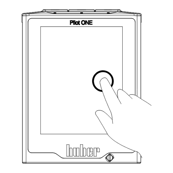
Function description Chapter 3 OPERATION MANUAL Display instruments Display instruments The following meters are available: ▪ >Touchscreen< [88] 3.7.1 The touchscreen [88] The most important display and operating instrument. Shows both standard variables (setpoint, actual value, setpoint thresholds...), and also menu guidance, error information output and opera- tion. -
Page 36: The Categories
Function description OPERATION MANUAL Chapter 3 3.8.2 The categories For clarity we have grouped the Operation and Setting of Pilot ONE in various categories. A category is selected by tapping it. 3.8.3 The sub-categories The sub-categories are parts of a category. This is where you will find the entries that we have grouped together for you in the selected category. -
Page 37: Copying The Settings To A Data Carrier
Function description Chapter 3 OPERATION MANUAL Start Tap on the “Start” touchbutton. Confirm the start of temperature control by tapping on “OK”. The correct selection will be displayed graphically and temperature control will start immediate- ly. If tapping on “OK” is not correct, this is displayed graphically for 2 seconds. After this, the dis- play will return to the “Home”... -
Page 38: Restore Factory Settings
Function description OPERATION MANUAL Chapter 3 Confirm the selection of the file by tapping on “OK”. Select the setting group to be loaded from the list. A multiple selection is possible. Confirm your choice by tapping on “OK”. ... -
Page 39: Restore To Factory Settings Without Overtemperature Protection
Function description Chapter 3 OPERATION MANUAL Description Configuration manual parameters Protective function High Limit Alarm Internal; Low Limit Alarm Internal; High Limit Alarm Process; Low Limit Alarm Process; Hydrostatic Correction; Warning – – – Time Limit (CC-E only); Min. Level (for temperature control units with analogue level sensor);... - Page 40 Function description OPERATION MANUAL Chapter 3 Read the safety warning and confirm by tapping on “OK”. Read the Note and confirm by tapping on “OK”. Tap on the temperature format set by you in the controller (green text). ...
-
Page 41: Setup Mode
Setup mode Chapter 4 OPERATION MANUAL Setup mode Setup mode Moving the temperature control unit during operation SERIOUS BURNS/FREEZING OF THE HOUSING PARTS/ESCAPING THERMAL FLUID Do not move temperature control units that are in operation. 4.1.1 Turning on the temperature control unit PROCEDURE ... -
Page 42: Setting The Overtemperature Protection
Set the cut-out value of the overtemperature protection at least 25 K below the combustion point of the thermal fluid. The maximum settable cut-out value of the OT corresponds, for Huber thermal fluids, to the speci- fied upper working temperature of the thermal fluid. The usable working temperature range may be less, if the overtemperature protection is correctly set. -
Page 43: Setting "Ot Expansion Vessel
Setup mode Chapter 4 OPERATION MANUAL Read the safety warning and confirm by tapping on “OK”. Read the Note and confirm by tapping on “OK”. Tap on the dialog entry “OT limit: heating”. Confirm your choice by tapping on “OK”. ... -
Page 44: Testing Overtemperature Protection For Functionality
Setup mode OPERATION MANUAL Chapter 4 4.1.4 Testing overtemperature protection for functionality Overtemperature protection (OT) does not trip MORTAL DANGER FROM FIRE Test the response of the device every month and after each change of the thermal fluid in order to assure proper functioning. -
Page 45: Select Temperature Control: Internal Or Process
Setup mode Chapter 4 OPERATION MANUAL additional RS485 interface is added to your temperature control unit. Optionally you can integrate the temperature control unit in a Profibus environment. For more information, see the pages from 63, section »Interfaces and software update«. The capacity adjustment of the temperature control unit is optimized so that the specified pro- cesses are run through in the fastest possible time. -
Page 46: Delta T Limiter
If the adjustment of the temperature does not correspond to the quality of the illustrations shown above, you can adjust the control parameters. With Huber temperature control units, there are various ways of finding the optimum control parameters. Depending on the facilities of the tempera- ture control unit, you can choose the following processes: ▪... -
Page 47: Sub-Category: "Select Auto/Expert Mode
Setup mode Chapter 4 OPERATION MANUAL 4.2.7 Sub-category: “Select auto/expert mode”. Use of the “Expert mode” without a thorough knowledge of I&C technology. MATERIAL DAMAGE TO THE APPLICATION Only use this mode if you have a thorough knowledge of I&C technology. Here you can select whether the control parameters are set in the “Automatic mode”... - Page 48 Setup mode OPERATION MANUAL Chapter 4 Enter a new setpoint using the number keypad that appears. This should be at least 10 K away from the current setpoint. Confirm your entry by tapping on “OK”. Setting of the control parameters using “Fast Identifica- tion”...
-
Page 49: Sub-Category: "Control Dynamics
Setup mode Chapter 4 OPERATION MANUAL PROCEDURE Before setting the control parameters, make sure that the temperature control unit has reached the set setpoint and has been controlling the temperature at this setpoint for a few minutes. Do not stop the temperature control. ... -
Page 50: Sub-Category: "Fluid Properties
Setup mode OPERATION MANUAL Chapter 4 Internal, dynamic temperature control with possible over- shooting of the tem- perature PROCEDURE Go to the “Categories Menu”. Tap on the category “Temperature Control”. Tap on the category “TAC/Manual”. Tap on the sub-category “Configuration auto”. ... -
Page 51: Sub-Category: "Display Parameters
Setup mode Chapter 4 OPERATION MANUAL 4.2.8.3.3 Sub-category: “VPC/Bypass” Under this entry, you can specify whether you use a bypass or not. PROCEDURE Go to the “Categories Menu”. Tap on the category “Temperature Control”. Tap on the category “TAC/Manual”. ... - Page 52 Setup mode OPERATION MANUAL Chapter 4 4.2.9.1.1 Sub-category: “Internal” Enter the new values for “KP”, “Tn” and “Tv” here one after the other. PROCEDURE Go to the “Categories Menu”. Tap on the category “Temperature Control”. Tap on the category “TAC/Manual”. ...
-
Page 53: Sub-Category: "Display Parameters
Sub-category: “Control structure” With this function, you have two different control structures available. “Huber PID controller”: Default setting “Classic PID controller”:This setting is exclusively used by Huber service engineers for service pur- poses. PROCEDURE Go to the “Categories Menu”. -
Page 54: 4.2.12 Setting The Setpoint Thresholds
Setup mode OPERATION MANUAL Chapter 4 4.2.12 Setting the setpoint thresholds Overview of the temperature thresh- olds The limits for the minimum and maximum setpoints serve for the safety of your system. They should be set for the application field of the thermal fluid before starting the first temperature control and when changing the thermal fluid. -
Page 55: Filling, Venting, Degassing And Draining
Isolate the temperature control unit from the power supply. Have the temperature control unit only serviced and cleaned by staff trained by Huber. If this is not complied with, it is assumed that the temperature control unit does not comply with all requirements of DIN EN 61010-2-010. - Page 56 Setup mode OPERATION MANUAL Chapter 4 Fill levels in the [23] >Sight glass< ▪ During the fill process, ensure any necessary measures, such as earthing the tanks, funnels and other aids, have been taken. ▪ Fill to the lowest possible height. PROCEDURE ...
-
Page 57: Degassing Externally Closed Applications
We recommend inert gas overlay for your temperature control unit. For this we offer the sealing set for Unistats in the Huber catalog (order No. 9402). The thermal fluid is protected from environmental influences when using a Unistat. This prevents an increased accumulation of moisture or the oxidative degradation of the thermal fluid. - Page 58 Setup mode OPERATION MANUAL Chapter 4 Under the category “Safety” in the section “Overtemperature”, the cut-out value of the installed temperature sensor can be set up to 100 °C in the degassing mode. In normal mode, only max. 70 °C can be set for the >Expansion vessel<...
-
Page 59: Draining Externally Closed Applications
Setup mode Chapter 4 OPERATION MANUAL Tap on the category “Start/Stop”. Tap on the dialog entry “Stop degassing”. Confirm your choice by tapping on “OK”. Read the note and confirm by tapping on “OK”. Degassing stops immediately and the pump continues to run for approx. - Page 60 Setup mode OPERATION MANUAL Chapter 4 PROCEDURE Temperature control units with >Emptying of residues< [10] Attach a suitable drain hose to the >Drain< [8]. Place the other end of the hose in a suitable container (e.g. original canister, which is compatible with the thermal fluid).
-
Page 61: Normal Operation
Normal operation Chapter 5 OPERATION MANUAL Normal operation Automatic operation Operating the temperature control units without the isolating sleeve installed BURNS/FROSTBITES FROM OVERFLOWING THERMAL FLUID AND/OR A HOT EXPANSION VESSEL Before using the temperature control unit: Check that the >Isolating sleeve< [27] is mounted in the >Filling port<... -
Page 62: Temperature Control Via A Created Temperature Control Program
Normal operation OPERATION MANUAL Chapter 5 is not correct, this is displayed graphically for 2 seconds. After this, the display will return to the “Home” screen again. Try to stop the temperature control unit again. The compressor is not switched off until the stepper motor valve has reached a defined position. The status line [Field 10] displays the relevant information. -
Page 63: Interfaces And Software Update
Only connect components that meet the specifications of the interface used. The use of PB commands is described in our “Data communications PB” manual. This manual can be downloaded from www.huber-online.com. Interfaces at the “Pilot ONE®” controller The Pilot ONE controller is not operated behind a firewall PROPERTY DAMAGE ... -
Page 64: Usb-2.0 Interface, Host
In this context, safety-critical thresholds for the temperature control fluid must be strictly observed. The control results contained in the data sheet can only be achieved with shielded sensor leads. We recommend the external Pt100 process control sensor from the Huber accessories program. Pin assignment (front view) -
Page 65: Service Interface
Chapter 6 OPERATION MANUAL 6.2.2 Service interface This interface is exclusively used by Huber service engineers for service purposes. An adapter cable makes this interface a RS232 serial port. 6.2.3 Connector POKO (floating contact) alarm Signal contact for external monitoring. -
Page 66: Jack Ecs (External Control Signal) Standby
Interfaces and software update OPERATION MANUAL Chapter 6 ▪ “Solenoid valve flow / return flow”: This function is used to control a connected solenoid valve. It takes 60 seconds before the POKO switches on after you have started the pump in the tempera- ture control unit. -
Page 67: Interfaces At The "Unistat® Tr401, Tr402
Information on the interface can be found on page 64 in Section »Connection jack for Pt100 process controller sensor«. 6.3.1.2 Service interface This interface is exclusively used by Huber service engineers for service purposes. An adapter cable makes this interface a RS232 serial port. V2.3.0en/22.07.19//17.12 Unistat® TR... -
Page 68: Control Connection Ht-Circulator/Controller
“Con- troller” 6.3.2.1 Service interface This interface is exclusively used by Huber service engineers for service purposes. An adapter cable makes this interface a RS232 serial port. 6.3.2.2 Connector POKO (floating contact) alarm Information on the interface can be found on page 65 in Section »Connector POKO (floating contact) alarm«. -
Page 69: Control Connection Ht-Circulator/Controller
Interfaces and software update Chapter 6 OPERATION MANUAL 6.3.2.5 Control connection HT-Circulator/Controller This interface is used to connect the HT-Circulator to the controller. For more information please refer to page 26 in Section »Connecting the temperature control unit with the controller (only TR401, TR402)«. -
Page 70: Jack Level (Com.g@Te® External Only)
Interfaces and software update OPERATION MANUAL Chapter 6 6.4.1 Jack LEVEL (Com.G@te® external only) For level monitoring in the >Sight glass< [23]. This connection enables you to connect an external float switch (Order No. 6152), which is posi- tioned in the >Sight glass< [23], for monitoring the level of your externally closed application. Acti- vation via a potential-free contact. -
Page 71: Jack Ecs (External Control Signal) Standby
Pin assignment Signal Description Wiring RS232 Receive Data Transmit Data Signal GND Wiring RS485 A with 120-Ω terminating resistor – – – Firmware update An instruction for running a firmware update can be found at www.huber-online.com. V2.3.0en/22.07.19//17.12 Unistat® TR... -
Page 72: Service/Maintenance
Service/maintenance OPERATION MANUAL Chapter 7 Service/maintenance Messages from the temperature control unit Messages output by the temperature control unit can be divided into various classes. Follow the instructions displayed on the >Touchscreen< [88]. Once a message has been acknowl- edged, a symbol is output on the >Touchscreen< [88]. Tapping the symbol takes you to an overview of all messages in chronological order. -
Page 73: Function Check And Visual Inspection
Carrying out maintenance work not described in this operation manual DAMAGE TO THE TEMPERATURE CONTROL UNIT For maintenance work not described in the operation manual, contact the Huber company. Maintenance work not described in this operation manual is reserved for qualified specialists trained by Huber. -
Page 74: Replacing Temperature Control Or Coolant Hoses
Every 12 months water quality water quality available at: and/or opera- www.huber-online.com tors *A = Air cooling; W = Water cooling; U = Applicable only for Unistats 7.3.2 Replacing temperature control or coolant hoses Replace defective temperature control and/or coolant hoses before turning on the temperature control unit. -
Page 75: Empty The Drip Tray
Service/maintenance Chapter 7 OPERATION MANUAL Following inspection/cleaning, reinsert the hat-type strainer and fasten the cooling water supply line. Remove the collecting container from below the >Cooling water inlet< [13]. Open the customer’s shut-off valves in the cooling water supply and return lines. ... -
Page 76: Thermal Fluid Inspection
Service/maintenance OPERATION MANUAL Chapter 7 7.4.1 Thermal fluid inspection Thermal fluid is not inspected on a regular basis BURNS DUE TO REDUCED BOILING POINT Regularly check your thermal fluid whether it meets the specifications in the safety data sheet. Thermal fluid is not inspected on a regular basis DAMAGE TO THE HEAT EXCHANGER AND/OR ELECTROMECHANICAL PARTS. - Page 77 Service/maintenance Chapter 7 OPERATION MANUAL PROCEDURE Drain the temperature control unit as described on page 59 in section »Draining externally closed applications«. Residual thermal fluid can remain in the pump chamber and the internal lines after draining. Leave the temperature control unit with open valves for a while. ...
-
Page 78: Cleaning The Surfaces
Service/maintenance OPERATION MANUAL Chapter 7 Vent the temperature control unit as described on page 55 in Section »Filling and venting exter- nally closed application«. An externally open application does not need to be vented. Start the function „Degassing“, as described on page 57 in Section »Degassing externally closed applications«. -
Page 79: Decontamination/Repairs
The decontamination process depends on the type and quantity of the materials used. Consult the relevant safety data sheet. You will find a prepared return receipt at www.huber-online.com. As the responsible body you are responsible for carrying out decontamination before third-party personnel come into contact with the temperature control unit / accessory. -
Page 80: Shutting Down
Shutting down OPERATION MANUAL Chapter 8 Shutting down Safety instructions and basic principles Connection/adjustment to the power supply not carried out by an electrician and/or connection to a power socket without protective earth (PE) MORTAL DANGER FROM ELECTRIC SHOCK Have the connection/adjustment to the power supply carried out by an electrician. ... -
Page 81: Draining The Cooling Water
Shutting down Chapter 8 OPERATION MANUAL Draining the cooling water This section must be observed when using water-cooled temperature control units. 8.3.1 Draining process Pressurized cooling water connections RISK OF INJURY Wear your personnel protective equipment (e.g. safety goggles). ... -
Page 82: Disposal
(e.g. refrigeration and air conditioning com- panies). Huber temperature control units and Huber accessories are made of high quality, recyclable materi- als. For example: Stainless steel 1.4301 / 1.4401 (V2A), copper, nickel, FKM, Perbunan, NBR, ceram- ic, carbon, Al-Oxid, red brass, brass, nickel-plated brass and silver solder. -
Page 83: Telephone Number: Customer Support
▪ Huber Italia: +39 0331 181493 ▪ Huber Swiss: +41 (0) 41 854 10 10 ▪ Huber UK: +44 1773 82 3369 ▪ Huber USA: +1 800 726 4877 | +1 919 674 4266 8.8.2 Telephone number: Sales Telephone: +49-781-9603-123 8.8.3... -
Page 84: Annex
Annex OPERATION MANUAL Chapter 9 Annex Unistat® TR V2.3.0en/22.07.19//17.12... - Page 86 Inspired by temperature designed for you Peter Huber Kältemaschinenbau AG Werner-von-Siemens-Str. 1 77656 O enburg / Germany Telefon +49 (0)781 9603-0 Telefax +49 (0)781 57211 info@huber-online.com www.huber-online.com Technischer Service: +49 (0)781 9603-244 -125 °C ...+425 °C...
Need help?
Do you have a question about the Unistat TR Series and is the answer not in the manual?
Questions and answers