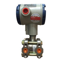
Sign In
Upload
Manuals
Brands
Honeywell Manuals
Transmitter
ST 3000
Honeywell ST 3000 Manuals
Manuals and User Guides for Honeywell ST 3000. We have
7
Honeywell ST 3000 manuals available for free PDF download: User Manual, Installation Manual, Specification And Model Selection Manual, Addendum
Honeywell ST 3000 User Manual (314 pages)
Smart Transmitter Release 300 and Smart Field Communicator Model STS103
Brand:
Honeywell
| Category:
Transmitter
| Size: 7.28 MB
Table of Contents
Patent Notice
3
References
4
Symbol Definitions
4
Table of Contents
5
Technical Assistance
13
Section 1 -Overview - First Time Users Only
15
Introduction
15
ST 3000 Smart Transmitters
16
Figure 1 Typical ST 3000 Differential Pressure Transmitter
16
Figure 2 Functional Block Diagram for Transmitter in Analog Mode of Operation
17
Figure 3 Functional Block Diagram for Transmitter in Digital de Mode of Operation
18
Table 1 ST 3000 Pressure Transmitter Family
20
Smart Field Communicator
22
Figure 4 Typical SFC Communication Interface
22
Table 2 SFC Model Differences
23
Transmitter/Sfc Order
25
Figure 5 Typical ST 3000 Transmitter and SFC Order Components
25
Local Smart Meter Options
27
Table 3 Local Smart Meter Available Options
27
Figure 6 ST 3000 with Local Smart Meter Option
28
Section 2 -Quick Start Reference
29
Introduction
29
Getting ST 3000 Transmitter On-Line Quickly
30
Table 4 Start-Up Tasks Reference
30
Section 3 -Preinstallation Considerations
31
Introduction
31
CE Conformity (Europe) Notice
32
Considerations for ST 3000 Transmitter
33
Figure 7 Typical Mounting Area Considerations Prior to Installation
33
Table 5 Operating Temperature Limits (Transmitters with Silicone Fill Fluids)
34
Table 6 Transmitter Overpressure Ratings
35
Considerations for SFC
36
Table 7 Installing and Charging SFC Battery Pack
37
Considerations for Local Smart Meter Option
38
Table 8 Local Smart Meter Specifications
38
Section 4 -Installation
39
Introduction
39
Mounting ST 3000 Transmitter
40
Figure 8 Typical Bracket Mounted and Flange Mounted Installations
40
Table 9 Mounting ST 3000 Transmitter to a Bracket
41
Figure 9 Leveling a Model STA122 or STA922 Absolute Pressure Transmitter
44
Table 10 Zero Corrects Procedure for STD110
46
Figure 10 Typical Flange Mounted Transmitter Installation
47
Figure 11 Typical Flush Mounted Transmitter Installation
48
Figure 12 Typical Pipe and Flange Mounted Installations
49
Table 11 Mounting Remote Diaphragm Seal Transmitter
50
Figure 13 Typical Remote Diaphragm Seal Transmitter Installation
51
Piping ST 3000 Transmitter
52
Figure 14 Typical 3-Valve Manifold and Blow-Down Piping Arrangement
52
Figure 15 Typical Piping Arrangement for ½" NPT Process Connection
53
Table 12 Suggested Transmitter Location for Given Process
53
Table 13 Process Connections
54
Table 14 Flange Description
55
Table 15 Installing Flange Adapter
56
Wiring ST 3000 Transmitter
57
Figure 16 Operating Range for ST 3000 Transmitters
57
Figure 17 ST 3000 Transmitter Terminal Block
58
Table 16 Wiring the Transmitter
59
Figure 18 Ground Connection for Lightning Protection
60
Section 5 -Getting Started
63
Introduction
63
Establishing Communications
64
Figure 19 Typical SFC Connections
64
Table 17 Starting Communications with Transmitter
65
Making Initial Checks
68
Table 18 Confirming Mode of Operation and Identifying Software Versions
68
Figure 20 Write Protect Jumper Location and Selections
69
Figure 21 Display with All Indicators Lit
70
Changing Mode of Operation
71
Table 19 Changing Mode of Operation
71
Figure 22 Keystroke Summary for Changing Mode of Operation
72
Section 6 -Configuration
73
Introduction
73
Overview
74
Figure 23 Summary of Configuration Process
74
Figure 24 SFC and ST 3000 Transmitter Memories
75
Table 20 Summary of Pressure Transmitter Configuration Parameters
77
Overview
77
Figure 25 Flowchart - ST 3000 Pressure Transmitter Configuration
80
Entering a Tag Number
85
Table 21 Entering Tag Number
85
Figure 26 Keystroke Summary for Entering Tag Number
86
Selecting Output Form
87
Table 22 Selecting Output Conformity
87
Figure 27 Keystroke Summary for Selecting Output Conformity
88
Figure 28 Square Root Dropout Points
89
Adjusting Damping Time
90
Table 23 Adjusting Damping Time
90
Figure 29 Keystroke Summary for Adjusting Damping Time
91
Selecting Unit of Measurement
92
Table 24 Pre-Programmed Engineering Units for Selection
92
Setting Range Values Using SFC
94
Table 25 Keying in LRV and URV
94
Figure 30 Keystroke Summary for Keying in LRV and URV
95
Table 26 Setting LRV and URV to Applied Pressures
96
Figure 31 Keystroke Summary for Setting LRV and URV to Applied Pressures
97
Setting Range Values Using Local Adjustments
98
Table 27 Setting Range Values Using Local Zero and Span Adjustments
98
Figure 32 Typical Setup for Setting Range Values Using Local Zero and Span Adjustments
104
Selecting Output Signal Mode (de Mode Only)
105
Table 28 Selecting Mode of Output Signal Indication
105
Figure 33 Keystroke Summary for Selecting Mode of Output Signal Indication
107
Selecting Message Format (de Mode Only)
108
Table 29 Selecting Message Format
108
Figure 34 Keystroke Summary for Selecting Message Format
109
Configuring Smart Meter Using SFC
110
Table 30 Setting up Local Smart Meter Configuration Using an SFC
111
Figure 35 Keystroke Summary for Configuring Local Smart Meter
116
Configuring Smart Meter Using Pushbuttons
117
Table 31 Smart Meter Pushbutton Description
117
Table 32 Smart Meter Engineering Units Code
119
Table 33 Selecting Engineering Units
120
Table 34 Smart Meter Restrictions for Setting Display Values
123
Table 35 Setting Lower Display Values for Smart Meter Display
124
Table 36 Setting Upper Display Value for Smart Meter Display
128
Figure 36 Button Pushing Summary for Selecting Engineering Units
134
Figure 37 Button Pushing Summary for Setting Lower and Upper Display Limits
135
Disconnecting SFC
136
Section 7 -Startup
137
Introduction
137
Startup Tasks
138
Table 37 Startup Procedure Reference
138
Running Analog Output Check
139
Table 38 Using Transmitter in Constant-Current Source Mode
139
Figure 38 Typical SFC and Meter Connections for Constant-Current Source Mode
141
Flow Measurement with DP Transmitter
142
Figure 39 Typical Piping Arrangement for Flow Measurement with DP Type Transmitter
142
Table 39 Starting up DP Transmitter for Flow Measurement with SFC
142
Pressure Measurement with DP Transmitter
145
Figure 40 Typical Piping Arrangement for Pressure Measurement with DP Type Transmitter
145
Table 40 Starting up DP Transmitter for Pressure Measurement with SFC
145
Liquid Level Measurement - Vented Tank
147
Figure 41 Typical Piping Arrangement for Liquid Level Measurement with DP Type Transmitter and Vented Tank
147
Table 41 Starting up DP Transmitter for Liquid Level Measurement in Vented Tank
148
Liquid Level Measurement - Pressurized Tank
150
Figure 42 Typical Piping Arrangement for Liquid Level Measurement with DP Type Transmitter and Pressurized Tank
150
Table 42 Starting up DP Transmitter for Liquid Level Measurement in Pressurized Tank
151
Pressure or Liquid Level Measurement with GP Transmitter
154
Figure 43 Typical Piping Arrangement for Pressure Measurement with GP Type Transmitter
154
Figure 44 Typical Piping Arrangement for Liquid Level Measurement with GP Typetransmitter
154
Table 43 Starting up GP Transmitter for Pressure or Liquid Level Measurement with SFC
155
Pressure or Liquid Level Measurement with Flush Mount Transmitter
158
Figure 45 Typical Arrangement for Pressure Measurement with Flush Mount Transmitter
158
Figure 46 Typical Arrangement for Liquid Level Measurement with Flush Mount Transmitter
158
Pressure Measurement with AP Transmitter
159
Figure 47 Typical Piping Arrangement for Pressure Measurement with AP Type Transmitter
159
Table 44 Starting up AP Transmitter for Pressure Measurement with SFC
159
Liquid Level Measurement with DP Transmitter with Remote Seals
161
Table 45 Starting up DP Transmitter with Remote Seals for Liquid Level Measurement with SFC
162
Section 8 -Operation
165
Introduction
165
Accessing Operation Data
166
Table 46 Summary of Keystrokes for Operation Data Access
166
Changing Default Failsafe Direction
169
Table 47 Cutting Failsafe Direction Jumper
170
Writing Data in Scratch Pad Area
171
Table 48 Writing Data in Scratch Pad Area
171
Saving and Restoring a Database
173
Table 49 Saving and Restoring a Database
174
Monitoring Local Smart Meter Display
177
Section 9 -Maintenance
183
Introduction
183
Preventive Maintenance
184
Inspecting and Cleaning Barrier Diaphragms
185
Replacing PWA
189
Replacing Meter Body
192
Advertisement
Honeywell ST 3000 User Manual (338 pages)
Smart Transmitter Release 300 and Smart Field Communicator Model STS103
Brand:
Honeywell
| Category:
Transmitter
| Size: 7.16 MB
Table of Contents
Patent Notice
3
References
4
Symbol Definitions
4
Table of Contents
5
Technical Assistance
13
Section 1 -Overview - First Time Users Only
15
Introduction
15
ST 3000 Smart Transmitters
16
Figure 1 Typical ST 3000 Differential Pressure Transmitter
16
Table 1 ST 3000 Pressure Transmitter Family
20
Smart Field Communicator
22
Typical SFC Communication Interface
22
Transmitter/Sfc Order
25
Local Smart Meter Options
27
Figure 6 ST 3000 with Local Smart Meter Option
28
Section 2 -Quick Start Reference
29
Introduction
29
Getting ST 3000 Transmitter On-Line Quickly
30
Table 4 Start-Up Tasks Reference
30
Section 3 -Preinstallation Considerations
31
Introduction
31
CE Conformity (Europe) Notice
32
Considerations for ST 3000 Transmitter
33
Typical Mounting Area Considerations Prior to Installation
33
Considerations for SFC
36
Table 7 Installing and Charging SFC Battery Pack
36
Considerations for Local Smart Meter Option
38
Section 4 -Installation
39
Introduction
39
Typical Bracket Mounted and Flange Mounted Installations
40
Mounting ST 3000 Transmitter
44
Leveling Absolute Pressure Transmitter
44
Table 10 Zero Corrects Procedure for STD110
46
Typical Flange Mounted Transmitter Installation
47
Figure 11 Typical Flush Mounted Transmitter Installation
48
Typical Pipe and Flange Mounted Installations
49
Table 11 Mounting Remote Diaphragm Seal Transmitter
50
Figure 13 Typical Remote Diaphragm Seal Transmitter Installation
51
Piping ST 3000 Transmitter
52
Typical 3-Valve Manifold and Blow-Down Piping Arrangement
52
Table 14 Flange Description
55
Wiring ST 3000 Transmitter
57
Figure 16 Operating Range for ST 3000 Transmitters
57
ST 3000 Transmitter Terminal Block
58
Figure 18 Ground Connection for Lightning Protection
60
Section 5 -Getting Started
64
Introduction
64
Establishing Communications
65
Typical SFC Connections
65
Table 17 Starting Communications with Transmitter
66
Making Initial Checks
69
Table 18 Confirming Mode of Operation and Identifying Software Versions
69
Figure 20 Write Protect Jumper Location and Selections
70
Display with All Indicators Lit
71
Changing Mode of Operation
72
Figure 22 Keystroke Summary for Changing Mode of Operation
73
Section 6 -Configuration
74
Introduction
74
Overview
75
Figure 24 SFC and ST 3000 Transmitter Memories
76
Figure 25 Flowchart - ST 3000 Pressure Transmitter Configuration
81
Entering a Tag Number
86
Table 21 Entering Tag Number
86
Figure 26 Keystroke Summary for Entering Tag Number
87
Selecting Output Form
88
Table 22 Selecting Output Conformity
88
Adjusting Damping Time
91
Selecting Unit of Measurement
93
Table 24 Pre-Programmed Engineering Units for Selection
93
Setting Range Values Using SFC
95
Table 25 Keying in LRV and URV
95
Table 26 Setting LRV and URV to Applied Pressures
97
Setting Range Values Using Local Adjustments
99
Table 27 Setting Range Values Using Local Zero and Span Adjustments
99
Selecting Output Signal Mode (de Mode Only)
106
Table 28 Selecting Mode of Output Signal Indication
106
Figure 33 Keystroke Summary for Selecting Mode of Output Signal Indication
108
Selecting Message Format (de Mode Only)
109
Table 29 Selecting Message Format
110
Configuring Smart Meter Using SFC
111
Table 30 Setting up Local Smart Meter Configuration Using an SFC
113
Configuring Smart Meter Using Pushbuttons
120
Table 35 Setting Lower Display Values for Smart Meter Display
125
Table 36 Setting Upper Display Value for Smart Meter Display
129
Figure 36 Button Pushing Summary for Selecting Engineering Units
135
Disconnecting SFC
137
Section 7 -Startup
138
Introduction
138
Startup Tasks
139
Running Analog Output Check
139
Table 38 Using Transmitter in Constant-Current Source Mode
140
Flow Measurement with DP Transmitter
143
Table 39 Starting up DP Transmitter for Flow Measurement with SFC
144
Pressure Measurement with DP Transmitter
146
Figure 40 Typical Piping Arrangement for Pressure Measurement with DP Type Transmitter
146
Table 40 Starting up DP Transmitter for Pressure Measurement with SFC
146
Liquid Level Measurement - Vented Tank
148
Figure 41 Typical Piping Arrangement for Liquid Level Measurement with DP Type Transmitter and Vented Tank
148
Table 41 Starting up DP Transmitter for Liquid Level Measurement in Vented Tank
149
Liquid Level Measurement - Pressurized Tank
151
Figure 42 Typical Piping Arrangement for Liquid Level Measurement with DP Type Transmitter and Pressurized Tank
151
Table 42 Starting up DP Transmitter for Liquid Level Measurement in Pressurized Tank
152
Pressure or Liquid Level Measurement with GP Transmitter
155
Figure 43 Typical Piping Arrangement for Pressure Measurement with GP Type Transmitter
155
Figure 44 Typical Piping Arrangement for Liquid Level Measurement with GP Typetransmitter
155
Table 43 Starting up GP Transmitter for Pressure or Liquid Level Measurement with SFC
156
Pressure or Liquid Level Measurement with Flush Mount Transmitter
159
Figure 45 Typical Arrangement for Pressure Measurement with Flush Mount Transmitter
159
Figure 46 Typical Arrangement for Liquid Level Measurement with Flush Mount Transmitter
159
Pressure Measurement with AP Transmitter
160
Figure 47 Typical Piping Arrangement for Pressure Measurement with AP Type Transmitter
160
Table 44 Starting up AP Transmitter for Pressure Measurement with SFC
160
Liquid Level Measurement with DP Transmitter with Remote Seals
162
Table 45 Starting up DP Transmitter with Remote Seals for Liquid Level Measurement with SFC
165
Section 8 -Operation
166
Introduction
166
Accessing Operation Data
167
Changing Default Failsafe Direction
168
Changing Default Failsafe Direction
170
Table 47 Cutting Failsafe Direction Jumper
171
Writing Data in Scratch Pad Area
172
Table 48 Writing Data in Scratch Pad Area
173
Saving and Restoring a Database
174
Table 49 Saving and Restoring a Database
177
Monitoring Local Smart Meter Display
180
Section 9 -Maintenance
183
Introduction
183
Preventive Maintenance
184
Inspecting and Cleaning Barrier Diaphragms
185
Replacing PWA
189
Honeywell ST 3000 User Manual (240 pages)
Smart Transmitter
Brand:
Honeywell
| Category:
Transmitter
| Size: 6.01 MB
Table of Contents
Patent Notice
2
About this Document
3
Symbol Definitions
4
Table of Contents
5
1 Introduction - First Time Users Only
15
Overview
15
ST 3000 Smart Transmitters
16
Figure 1 Typical ST 3000 Differential Pressure Transmitter
16
Figure 2 Functional Block Diagram for Transmitter in Analog Mode of Operation
17
Table 1 ST 3000 Pressure Transmitter Family
19
HART Communicator
21
Figure 3 Typical Communication Interface
21
Transmitter Order
22
Figure 4 Typical ST 3000 Transmitter Order Components
22
Local Smart Meter Option
23
Figure 5 ST 3000 with Local Smart Meter Option
23
Table 2 Local Smart Meter Options
24
2 Quick Start Reference
25
Overview
25
Getting ST 3000 Transmitter On-Line Quickly
26
Table 3 Start-Up Tasks Reference
26
3 Preinstallation Considerations
27
Overview
27
CE Conformity (Europe) Notice
27
Considerations for ST 3000 Transmitter
28
Figure 6 Typical Mounting Area Considerations Prior to Installation
28
Table 4 Operating Temperature Limits (Transmitters with Silicone Fill Fluid DC200)
29
Considerations for HART Communicator
30
Considerations for Local Smart Meter Option
30
Table 5 Transmitter Maximum Allowable Working Pressure (MAWP) Ratings
30
4 Installation
31
Overview
31
Mounting ST 3000 Transmitter
31
Table 6 Mounting ST 3000 Transmitter to a Bracket
32
Figure 7 Typical Bracket Mounted and Flange Mounted Installations
32
Table 7 Zero Corrects Procedure for Transmitters with a Small Differential Pressure Span
35
Figure 8 Leveling Transmitters
35
Figure 9 Typical Flange Mounted Transmitter Installation
37
Table 8 Flush Mount Transmitter Installation
38
Figure 10 Typical Flush Mounted Transmitter Installation
38
Figure 11 Typical Flange and Pipe Mounted Installations
39
Table 9 Mounting Remote Diaphragm Seal Transmitter
40
Figure 12 Typical Remote Diaphragm Seal Transmitter Installation
41
Piping ST 3000 Transmitter
42
Figure 13 Typical 3-Valve Manifold and Blow-Down Piping Arrangement
42
Table 10 Suggested Transmitter Location for Given Processes
43
Figure 14 Typical Piping Arrangement for ½" NPT Process Connection
43
Table 11 Process Connections
44
Table 12 Flange Description
45
Table 13 Installing Flange Adapter
46
Wiring ST 3000 Transmitter
47
Figure 15 Operating Range for ST 3000 Transmitters
47
Figure 16 ST 3000 Transmitter Terminal Blocks
48
Table 14 Wiring the Transmitter
49
Figure 17 Ground Connection for Lightning Protection
50
5 Getting Started
53
Overview
53
Establishing Communications
53
Figure 18 Typical Communicator Connections
54
Table 15 Starting Communications with Transmitter
55
Making Initial Checks
56
Table 16 Reviewing Factory-Set Configuration Parameters
56
Figure 19 Write Protection and Failsafe Direction Jumper Location
57
Figure 20 Smart Meter Display with All Indicators Lit
58
6 Configuration
59
Overview
59
Configuration Overview
60
Figure 21 Summary of Configuration Process
60
Figure 22 Communicator and ST 3000 Transmitter Memories
61
Table 17 Summary of Pressure Transmitter Configuration Parameters
62
Figure 23 Online (or HOME) Menu Summary
64
Figure 24 HART Communicator Menu Summary
65
Figure 25 HART Communicator Keyboard
66
Tag- Entering a Tag Number
69
Table 18 Entering Tag Number
69
PV Unit- Selecting Unit of Pressure Measurement
70
Table 19 Selecting Engineering Units
70
Range Values- Setting PV URV and PV LRV
71
Table 20 Keying in LRV and URV
71
Table 21 Setting LRV and URV to Applied Pressures
72
Device Information
73
Table 22 Viewing/Entering Device Information Data
73
Pressure Transfer Function- Selecting Output Conformity
74
Table 23 Selecting Output Conformity
74
Figure 26 Square Root Dropout Point
75
PV Damping- Adjusting Damping Time
76
Table 24 Adjusting Damping Time
76
SV Units- Selecting Secondary Variable Units
77
Table 25 Selecting SV Temperature Units
77
Poll Addr- Selecting Poll Address
78
Disconnecting the Communicator
78
Table 26 Selecting Poll Address
78
7 Start-Up
79
Overview
79
Start-Up Tasks
80
Table 27 Start-Up Procedure Reference
80
Running Analog Output
81
Table 28 Using Transmitter in Constant-Current Source (Output) Mode
81
Figure 27 Typical Communicator and Meter Connections for Constant-Current Source (Output) Mode
82
Flow Measurement with DP Transmitter
83
Table 29 Starting up DP Transmitter for Flow Measurement
83
Figure 28 Typical Piping Arrangement for Flow Measurement with DP Type Transmitter
83
Pressure Measurement with DP Transmitter
85
Table 30 Starting up DP Transmitter for Pressure Measurement
85
Figure 29 Typical Piping Arrangement for Pressure Measurement with DP Type Transmitter
85
Liquid Level Measurement - Vented Tank
87
Table 31 Starting up DP Transmitter for Liquid Level Measurement in Vented Tank
87
Liquid Level Measurement - Pressurized Tank
89
Figure 31 Typical Piping Arrangement for Liquid Level Measurement with DP Type Transmitter and Pressurized
89
Table 32 Starting up DP Transmitter for Liquid Level Measurement in Pressurized Tank
90
Pressure or Liquid Level Measurement with GP Transmitter
92
Figure 32 Typical Piping Arrangement for Pressure Measurement with GP Type Transmitter
92
Table 33 Starting up GP Transmitter for Pressure or Liquid Level Measurement
93
Figure 33 Typical Piping Arrangement for Liquid Level Measurement with GP Type Transmitter
93
Pressure Measurement with AP
95
Figure 34 Typical Piping Arrangement for Pressure Measurement with AP Type Transmitter
95
Table 34 Starting up AP Transmitter for Pressure Measurement
96
Liquid Level Measurement with DP Transmitter with Remote Seals
97
Table 35 Starting up DP Transmitter with Remote Seals for Liquid Level Measurement
97
Figure 35 Typical Piping Arrangement for Liquid Level Measurement with DP Type Transmitter with Remote
97
8 Operation
101
Introduction
101
Accessing Operation Data
101
Table 36 Summary of Keystrokes for Operation Data Access
102
Changing Default Failsafe Direction and Write Protect Jumpers
104
Figure 36 Location of Failsafe and Write Protect Jumpers on PWA
104
Table 37 Changing Default Failsafe Direction or Write Protect Jumper
105
Writing Data in the Message Area
106
Table 38 Writing Data in the Message Area
106
Saving and Restoring a Configuration Database
107
Figure 37 Summary of Save and Restore Database Function
107
Table 39 Saving a Configuration Database
108
Table 40 Downloading a Configuration Database
109
9 Maintenance
111
Introduction
111
Preventive Maintenance
111
Inspecting and Cleaning Barrier Diaphragms
111
Table 41 Inspecting and Cleaning Barrier Diaphragms
112
Figure 38 Disassembly of DP Transmitter Process Heads from Meter Body
113
Replacing Printed Wiring Assembly (PWA)
114
Table 42 Process Head Bolt Torque Ratings
114
Table 43 Replacing PWA
114
Replacing Meter Body
117
Table 44 Replacing Meter Body Only
117
10 Calibration
121
Introduction
121
Overview
121
Calibrating Analog Output Signal
122
Table 45 Calibrating Output Signal for Transmitter in Analog Mode
122
Calibrating Range
123
Table 46 Calibrating Measurement Range
123
Figure 39 Typical Range Calibration Hookup
124
Resetting Calibration
125
Table 47 Resetting Calibration Data
125
11 Troubleshooting
127
Introduction
127
Troubleshooting Overview
127
To Access Transmitter Diagnostics
127
Diagnostic Messages
128
Table 48 Summary of Diagnostic Messages for Critical Failures
128
Table 49 Summary of Diagnostic Messages for Non-Critical Failures
129
Table 50 Summary of Diagnostic Messages for Communication Errors
129
Interpreting Messages
130
Table 51 Diagnostic Message Interpretation Table
130
Clearing Critical Status
132
Table 52 Resetting the Transmitter
132
12 Parts List
133
Replacement Parts
133
Figure 40 Major ST 3000 Smart Transmitter Parts Reference
134
Std974
134
Figure 41 Major ST 3000 Smart Transmitter Parts Reference
135
Figure 42 Series 100/900 Electronics Housing - Electronics/Meter End
138
Figure 43 Series 100/900 Electronics Housing - Terminal Block End
138
Figure 44 Series 100 and Series 900 DP Meter Body for Models STD924 & STD930 C, D, G, H, K, and L and STD974
139
Figure 45 Series 900 DP Meter Body for Models STD924 & STD930 A, B, E, F, and J
142
Figure 46 Series 100 GP and AP Meter Bodies and Series 900 AP Meter Body
144
Figure 47 Series 900 Dual-Head GP Meter Bodies
146
13 Reference Drawings
151
Wiring Diagrams
151
Appendix A- Smart Meter Reference
153
Introduction
153
Smart Meter Display
155
Smart Meter Specifications
157
Setting Range Values (Local Zero and Span)
158
Configuring Smart Meter Using Pushbuttons
161
Setting Smart Meter Display Using the HART Communicator
174
Typical Smart Meter Indications
177
Operation Error Codes
178
Meter/Transmitter Interaction
179
Appendix B- Configuration Record Sheet
181
Appendix C - Freeze Protection of Transmitters
183
Possible Solutions/Methods
183
Advertisement
Honeywell ST 3000 Installation Manual (126 pages)
Smart Transmitter
Brand:
Honeywell
| Category:
Transmitter
| Size: 3.01 MB
Table of Contents
Patent Notice
3
References
4
Table of Contents
5
Technical Assistance
8
Transmitter Terminal Blocks
9
Section 1 -Getting Started
11
CE Conformity (Europe) Notice
11
Preliminary Checks
12
Section 2 -Optional Bench Check
15
Connecting Power and SCT/SFC
15
Figure 1 Typical Power Supply and SCT/SFC Connections to ST 3000
16
Table 1 Connecting Power Supply and SFC to ST 3000
16
Testing Communications
17
Table 2 Testing Communications with Transmitter
17
Verifying Configuration Data
20
Table 3 Verifying Transmitter's Configuration Data (Using the SFC)
20
Changing Default Failsafe Direction
23
Figure 2 Location of Failsafe Direction Jumper on PWA
24
Table 4 Cutting Failsafe Direction Jumper
24
Optional Write Protect Jumper
25
Figure 3 Write Protect Jumper Location and Selections
25
Setting Range Values Using Local Adjustments
26
Section 3 -Preinstallation Considerations
27
Considerations for ST 3000 Transmitter
27
Figure 4 Typical Mounting Area Considerations Prior to Installation
27
Table 5 Operating Temperature Limits (Transmitters with Silicone Fill Fluids)
28
Considerations for SFC/SCT
30
Table 7 Installing and Charging SFC Battery Pack
30
Considerations for Local Smart Meter Option
32
Section 4 -Installation
33
Mounting ST 3000 Transmitter
33
Figure 5 Typical Bracket Mounted and Flange Mounted Installations
33
Table 8 Mounting ST 3000 Transmitter to a Bracket
34
Figure 6 Leveling a Model STA122 or 922 Absolute Pressure Transmitter
37
Table 9 Zero Corrects Procedure for STD110
38
Figure 7 Typical Flange Mounted Transmitter Installation
39
Figure 8 Typical Flush Mounted Transmitter Installation
40
Figure 9 Typical Pipe and Flange Mounted Installations
41
Table 10 Mounting Remote Diaphragm Seal Transmitter
42
Figure 10 Typical Remote Diaphragm Seal Transmitter Installation
43
Piping ST 3000 Transmitter
44
Figure 11 Typical 3-Valve Manifold and Blow-Down Piping Arrangement
44
Figure 12 Typical Arrangement for ½" NPT Process Connection Piping
45
Table 11 Suggested Transmitter Location for Given Process
45
Table 12 Process Connections
46
Table 13 Flange Description
47
Table 14 Installing Flange Adapter
48
Wiring ST 3000 Transmitter
49
Figure 13 Operating Range for ST 3000 Transmitters
49
Figure 14 ST 3000 Transmitter Terminal Block
50
Table 15 Wiring the Transmitter
51
Figure 15 Ground Connection for Lightning Protection
52
Section 5 -Reference Drawings
55
Wiring Diagrams and Dimension Drawings
55
Appendix A Smart Meter Reference
61
Introduction
61
Smart Meter Display
62
Figure A-1 Smart Meter Display with All Indicators Lit
62
Table A-1 Smart Meter Pushbuttondescription
62
Smart Meter Specifications
63
Setting Range Values (Local Zero and Span)
64
Table A-3 Setting Range Values Using Local Zero and Span Adjustments
64
Figure A-2 Typical Setup for Setting Range Values Using Local Zero and Span Adjustments
68
Configuring Smart Meter Using Pushbuttons
69
Table A-4 Smart Meter Engineering Units Code
70
Table A-5 Selecting Engineering Units
71
Table A-6 Smart Meter Restrictions for Setting Display Values
73
Table A-7 Setting Lower Display Values for Smart Meter Display
74
Table A-8 Setting Upper Display Value for Smart Meter Display
78
Configuring Smart Meter Using SFC
83
Table A-9 Setting up Smart Meter Configuration Using an SFC
84
Configuring Smart Meter Using SCT 3000
89
Typical Smart Meter Indications
90
Table A-10 Summary of Typical Smart Meter Indications
90
Table A-11 Smart Meter Error Codes and Descriptions
91
Appendix B -Hazardous Locations Reference
93
North American Classification of Hazardous Locations
93
Table B-1 Factory Mutual (FM) Approval
97
Table B-2 Canadian Standards Association (CSA)
98
International Electrotechnical Commission (IEC) Classification of Hazardous Locations
99
Table B-3 CENELEC / LCIE Certification
101
Table B-4 Standards Australia (LOSC) Certification
102
Table B-5 Zone 2 (Europe) Declaration of Conformity
102
Enclosure Ratings
103
Table B-6 NEMA Enclosure Type Numbers and Comparable IEC Enclosure Classification
104
Index
105
Table 6 Transmitter Overpressure Ratings
108
Declaration of Conformity
121
ST3000/R300 Pressure Transmitters
122
Honeywell ST 3000 Specification And Model Selection Manual (36 pages)
Series 100 Remote Diaphragm Seals Models Smart Transmitter
Brand:
Honeywell
| Category:
Transmitter
| Size: 1.61 MB
Table of Contents
Specifications
5
Parameter Description
10
Application Data
15
Ordering Information
19
Warranty Options
28
Dimensions and Drawings
31
Honeywell ST 3000 Addendum (6 pages)
Smart Transmitter Release 300 with HART Communications Option
Brand:
Honeywell
| Category:
Transmitter
| Size: 0.27 MB
Honeywell ST 3000 User Manual (4 pages)
Smart Transmitter Release 300 with HART Communications Option
Brand:
Honeywell
| Category:
Transmitter
| Size: 0.15 MB
Advertisement
Related Products
Honeywell STT850 Series
Honeywell SmartLine STD720
Honeywell SmartLine STD770
Honeywell STGW73L
Honeywell STGW74L
Honeywell STAW740
Honeywell STAW74L
Honeywell STRW82D
Honeywell STRW73D
Honeywell STFW93D
Honeywell Categories
Thermostat
Controller
Control Unit
Security Camera
Accessories
More Honeywell Manuals
Login
Sign In
OR
Sign in with Facebook
Sign in with Google
Upload manual
Upload from disk
Upload from URL