Sign In
Upload
Manuals
Brands
Hiwin Manuals
Servo Drives
D1-N-09
Hiwin D1-N-09 Manuals
Manuals and User Guides for Hiwin D1-N-09. We have
3
Hiwin D1-N-09 manuals available for free PDF download: User Manual, Assembly And Commissioning Instructions
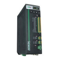
Hiwin D1-N-09 User Manual (283 pages)
Brand:
Hiwin
| Category:
Servo Drives
| Size: 21.37 MB
Table of Contents
Table of Contents
3
1 About this User Manual
7
General Precautions
8
HIWIN MIKROSYSTEM Corp
8
Risk Identification
9
Safety Precautions
10
2 Specifications
13
Safety Certificates and Model Explanations
14
Safety Certificates
14
Specifications
14
Nameplate Information
15
Model Explanation
16
Servo Drive Specification
17
Basic Specification
17
Dimensions
21
Installation
23
System Requirements
24
3 Operation Principles
25
Operation Mode
26
Position Mode
26
Velocity Mode
27
Force/Torque Mode
27
Stand-Alone Mode
27
Encoder Types
27
Encoder Signal Output
29
Path Planning
30
Servo Loops and Servo Gains
32
Gain Margin and Phase Margin
33
Nyquist Plot
33
Bode Plot
35
Move and Settling
36
Error Compensation
37
Velocity Ripple ···················································································································
38
Enabling
39
Basic Physical Quantities
40
4 Wiring
41
System Configuration and Wiring
42
System Connection
42
Wiring
42
Connector Specifications
45
Main Power (X1)
47
Regenerative Resistor and DC Link (X2)
50
Motor Power (X3)
53
Control Power and Brake (X4)
54
USB Communication (X5)
55
Control Signals (X6)
55
Digital Command
57
Programmable I/O
58
Encoder Output
60
PT Signal Output
61
Analog Command
61
Safety Function (X7, X8)
62
Motor Temperature Detection (X9)
68
Encoder (X10, X11, X12)
68
Ethercat/Modbus Communication (X13)
70
Accessories of D1-N Servo Drive
71
5 Servo Drive Configuration
79
Installation and Communication
80
Installing Lightening
80
Communication Setup
81
Main Window
85
Configuration Center
87
Setting Parameters of Motor
88
Setting Parameters of Encoder
93
Setting Hall Sensor
102
Setting Operation Mode
103
Setting Servo Drive
105
Modbus Communication Setting
107
Saving Configuration
108
Auto Phase Center
109
Inspection before Auto Phase Initialization
111
Operating Procedures for Auto Phase Initialization
112
Precautions for Auto Phase Initialization
116
I/O Setting
117
Digital Inputs
117
Digital Outputs
125
Setting In-Position Signal
129
Homing
132
Position Trigger Function
139
Save Parameters to Flash and Set to Factory Default
142
Save Parameters to Flash
142
Set Parameters to Factory Default
142
Setting Operation Mode Via Lightening
144
Position Mode
144
Velocity Mode
146
Force/Torque Mode
148
Stand-Alone Mode
149
6 Tuning
151
Status Display and Quick View
152
Status Display
152
Quick View
153
Function Keys
154
Performance Center
154
Scope
157
Data Collection
159
Function Description
159
Data Collection Via PDL Program
161
Plot View
162
Display Mode
162
Save and Open File
167
Calculation Functions
168
Advanced Gain Tuning
170
Filter
171
Acceleration Feedforward
173
Schedule Gains and Velocity Loop Gain
175
Offset Correction for Analog Input
178
Current Loop
179
Vibration Suppression Filter
179
Friction Compensation
183
Loop Constructor
184
Load/Save File
185
Tool
187
Filter
190
Gain Tuning
192
Spectrum Analysis
193
Checking Encoder Signal
194
Error Map Function
195
Setting Error Map Function
195
Enabling Error Map Function
198
Saving and Opening Error Map Table
199
Changing the Start Position of Error Map Function
199
Compensation Function for Resolver Signal ·············································································
204
Operational Description
205
Enabling Signal Compensation Function
206
Saving and Opening Signal Compensation Table
206
Compensation Function for Absolute Resolver Signal
207
Operational Description
207
Enabling Signal Compensation Function
209
Saving and Opening Signal Compensation Table
209
7 LCD Display
211
LCD Panel
212
LCD Display Description
212
8 Protection Function
215
Motion Protection
216
Protection Function
216
Position and Velocity Error Protection
219
Position Error Limit
219
Position Error Warning and Velocity Error Warning
220
Brake Protection
220
Limit Protection
222
Hardware Limit Protection
222
Software Limit Protection
222
Over Temperature Protection
223
Motor over Temperature Protection
223
Software over Temperature Protection
224
Servo Drive over Temperature Protection
224
Overvoltage Protection
224
9 Errors and Warnings
227
Error Messages and Warning Messages
228
Error and Warning Log
233
Automatic Error Handling
236
Troubleshooting
237
Status Indicator
237
Error Description and Corrective Action
239
10 Advanced Frequency Analysis
243
Advanced Frequency Analysis ·····························································································
244
Frequency Analyzer
245
SMCL Tools
246
11 Enabling Motor
249
Enabling Method
250
Checking Enabling State from Lightening
251
12 Parameter Comparison
253
Comparing the Parameters in RAM and Flash
254
13 Updating Firmware and Loading PDL
257
Updating Servo Drive Firmware
258
Loading PDL Program
261
Updating Motor Parameters
263
14 Modbus Communication
265
Modbus Communication Specification
266
Function Codes
266
Modbus Communication
266
Modbus Object
270
Input Register
271
Holding Register
276
15 Motor Power Cable Shielding and Grounding
279
Motor Power Cable Shielding
280
Grounding
282
Advertisement
Hiwin D1-N-09 Assembly And Commissioning Instructions (183 pages)
Servo Drive Amplifier
Brand:
Hiwin
| Category:
Amplifier
| Size: 9.08 MB
Table of Contents
Table of Contents
3
1 Content
7
Version of this Documentation
7
Information about the Document
7
Requirements
7
Availability
8
Scope of Validity for These Assembly and Commissioning Instructions
8
Depiction of Safety Notices
8
Symbols Used
9
Warranty and Liability
9
Manufacturer's Details
10
Copyright
10
Product Monitoring
10
2 Safety
11
Intended Use
11
Disclaimer in the Event of Modification or Improper Use
12
Qualified Trained Staff
12
General Safety Notices
13
Safety Notices Regarding Storing the Drive Amplifiers
13
Safety Notices Regarding Transporting the Drive Amplifiers
13
Safety Notices Regarding Working with Energised and Live Products
14
Safety Notices Regarding Working with Hot Surfaces
14
Technical Support
14
3 Product Description
15
Order Code
16
Type Plates
17
Guidelines and Standards
18
Scope of Supply
18
Technical Specification
19
4 Assembly
21
Assembling the Drive Amplifier
21
Dimensions
22
Switch Cabinet Assembly
25
5 Electrical Connection
26
Overview of Electrical Connections
27
X1 - Mains Connection
29
1-Phase Mains Connection with Mains Filter
29
3-Phase Mains Connection with Mains Filter
30
X2 - Brake Resistor Connection
31
Brake Resistor Calculation
33
Dcbus Capacity of D1-N Servo Drives
33
X3 - Motor Connection
34
X4 - Control Voltage and Motor Brake Connection
35
X5 - Parameterisation Interface
36
X6 - Input and Output Connection
37
Wiring Variants for Step/Direction Input on X6
38
Switching Characteristics of Digital Inputs on the X6
39
Wiring of Encoder Output on X6
41
Wiring of Analogue Input on X6
41
X7 and X8 - STO Safety Function Connection
42
X9 - Motor Temperature Sensor
43
X10, X11, X12 - Encoder Connection
44
X13 - Ethercat
45
6 STO Safety Function
46
Definition STO
46
Functional Principle of the STO Function on the D1-N
47
Connections of STO Function on D1-N
47
Activation of the STO Function
50
Timing Diagram for Activating the STO Function
52
Timing Diagram for Releasing the STO Function
53
Preconditions for Using the Safety Function
53
Category 0 Stop 0
54
Category 1 Stop
54
Parking Brake Behaviour
54
Vertical Axes And/Or External Application of Force
54
Unintended Restart
54
Degree of Contamination When Using the Safety Function
54
Protected Cable Routing
55
Data for Maintenance Plans and Safety Calculations
55
Risk Analysis
56
Examples of Circuits for the STO Function
56
Safety Function Certified by TÜV
58
7 Ethercat
59
D1-N Ethercat with Coe Protocol
59
Integration of a D1-N in a Twincat Project
59
Installing the ESI File
59
Adding Devices by Scan
60
Setting the Axis Resolution
61
Setting the Maximum Speed
62
8 “Lightening” Commissioning Software
63
"Lightening" Commissioning Software
63
Installation of the Software
63
Initial Launch of the "Lightening" Software
65
Establishing Connection with Device
65
Operating Interface
67
The "Conf./Tune" Menu
69
The "Tools" Menu
70
The Shortcut Bar
71
Reset
71
Status
72
Errors and Warnings
72
Variable Rapid Access
72
Configuration Center" Without/With Ethercat
73
AC Servo Motor Parameterisation
74
Linear Motor Parameterisation
82
TM Motor Parameterisation
91
Motor Parameterisation with Endat 2.2 Encoder
100
Application Center
101
Homing
101
Backlash
109
Error Map
110
Resolver
112
Protection Center" (Limitations)
113
Protection
113
HW Limit Protection
114
Brake
114
Digital Inputs and Outputs / "I/O Center
116
Inputs
116
Outputs
117
9 Commissioning
119
Auto Phase Center
120
Servo Motors
122
Linear and Torque Motors
124
Frequency Analysis" - Automatically Adapting Control Parameters
128
Phase Initialisation" - First Commutation
133
SMCL Tool
133
LM and TM with Endat 2.2
135
Performance Center", Controller Parameter Optimisation
137
First Travel Subject to Control
139
Debounce Time" and "Target Radius" in the "Performance Center
140
Using the "Scope" Functions
141
Controller Tuning
148
Advanced Gains" - Filter
150
Setting Filters
151
Advanced Gains" - "Acc Feedforward
152
Advanced Gains" - "Schedule Gains + Vpg
154
Advanced Gains" - "Analog Input
155
Advanced Gains" - "Current Loop
156
Advanced Gains" - "VSF" (Velocity Suppression Function)
157
Advanced Gains" - "Friction Compens
158
Error History
160
10 Mega-Ulink Protocol
161
Features of the MPI Library
161
PDL (Process Description Language) Programming
162
Features of PDL Programming
162
Programming Examples (no Liability Accepted)
163
Writing PDL Program to D1-N and Saving
166
Stopping PDL Program, Allowing It to Run on and Deleting It
169
11 Troubleshooting
172
Error Codes and Troubleshooting
172
Warnings and Troubleshooting
175
Other Errors and Troubleshooting
178
12 Repair and Replacement
178
13 Parts Numbers and Accessories
179
Item Number for Drive Amplifier Set
179
Item Number for Connector Kit
180
Motor Cables
181
Cables for Encoder Systems
182
14 Declaration of Conformity
183
Hiwin D1-N-09 Assembly And Commissioning Instructions (160 pages)
Servo Drive Amplifier with EtherCAT and Safe Torque Off STO Safety Function
Brand:
Hiwin
| Category:
Amplifier
| Size: 15.34 MB
Table of Contents
Table of Contents
3
1 General Information
4
Information about the Document
4
Depictions Used in These Assembly Instructions
5
Warranty and Liability
7
Manufacturer's Details
7
Copyright
7
Product Monitoring
7
2 Basic Safety Notices
8
Intended Use
8
Disclaimer in the Event of Modification or Improper Use
8
Qualified Trained Staff
8
General Safety Notices
9
HIWIN Technical Support
10
Labels on D1-N Servo Drive Amplifier
10
3 Product Description
11
Order Code
11
Type Plates
12
Guidelines and Standards
13
Scope of Supply
13
Technical Specification
14
4 Assembly
16
Assembling the Drive Amplifier
16
Dimensions
16
Switch Cabinet Assembly
18
5 Electrical Connection
19
Overview of Electrical Connections
19
X1 - Mains Connection
21
X2 - Brake Resistor Connection
22
X3 - Motor Connection
26
X4 - Control Voltage and Motor Brake Connection
26
X5 - Parameterisation Interface
27
X6 - Input and Output Connection
28
X7 and X8 - STO Safety Function Connection
32
X9 - Motor Temperature Sensor
32
X10, X11, X12 - Encoder Connection
33
X13 - Ethercat
34
6 STO Safety Function
35
Definition STO
35
Functional Principle of the STO Function on the
35
Connections of STO Function on
36
Activation of the STO Function
37
Preconditions for Using the Safety Function
40
Examples of Circuits for the STO Function
42
Safety Function Certified by TÜV
44
7 Ethercat
45
D1-N Ethercat with Coe Protocol
45
8 “Lightening” Commissioning Software
49
Lightening" Commissioning Software
49
Installation of the Software
49
Initial Launch of the "Lightening" Software
50
Operating Interface
51
Configuration Center" Without Ethercat/With Ethercat
55
Application Center
78
Protection Center" (Limitations)
89
Digital Inputs and Outputs / "I/O Center
92
Commissioning
94
9 Commissioning
95
Auto Phase Center
95
Performance Center", Controller Parameter Optimisation
107
First Travel Subject to Control
109
Using the "Scope" Functions
110
Controller Tuning
116
Advanced Gains" - Filter
117
Error History
126
10 Mega-Ulink Protocol
127
Features of the MPI Library
127
PDL (Process Description Language) Programming
127
Features of PDL Programming
128
Programming Examples (no Liability Accepted))
128
Writing PDL Program to D1-N and Saving
131
Overview Advanced Parameters
135
Stopping PDL Program, Allowing It to Run on and Deleting It
141
11 Implementing the “Position Trigger”
143
Implementing the "Position Trigger
143
12 Troubleshooting
147
Error Codes and Troubleshooting
148
Warnings and Problem Rectification
150
Other Errors and Problem Rectification
151
13 Repair and Replacement
152
14 Parts Numbers and Accessories
153
Article Numbers for Drive Amplifier Sets
153
Article Numbers for Connector Kits
153
Article Numbers for Motor Cables
154
Cables for Encoder Systems
154
15 EC Declaration of Conformity
155
Advertisement
Advertisement
Related Products
Hiwin D1-N Series
Hiwin D1-N-18
Hiwin D1-N-36
Hiwin D1-N-90
Hiwin D1
Hiwin D2-DNN46A
Hiwin D2-DNN47A
Hiwin D2-DNN48A
Hiwin D2-DNN43A
Hiwin D2-DNN45A
Hiwin Categories
Robotics
Servo Drives
Engine
Industrial Equipment
Controller
More Hiwin Manuals
Login
Sign In
OR
Sign in with Facebook
Sign in with Google
Upload manual
Upload from disk
Upload from URL