Hitachi HTS721010G9AT00 Manuals
Manuals and User Guides for Hitachi HTS721010G9AT00. We have 2 Hitachi HTS721010G9AT00 manuals available for free PDF download: Specifications, Quick Installation Manual
Hitachi HTS721010G9AT00 Specifications (225 pages)
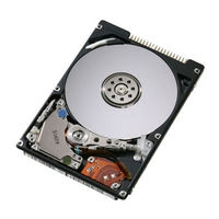
2.5 inch ATA/IDE hard disk drive
Table of Contents
Advertisement
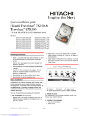
Hitachi HTS721010G9AT00 Quick Installation Manual (2 pages)
2.5 inch ATA/IDE & SATA hard disk drive
Advertisement