Sign In
Upload
Manuals
Brands
Hioki Manuals
Measuring Instruments
PW3390
User Manuals: Hioki PW3390 Power Analyzer
Manuals and User Guides for Hioki PW3390 Power Analyzer. We have
4
Hioki PW3390 Power Analyzer manuals available for free PDF download: Instruction Manual, Measurement Manual, Firmware Update Procedures
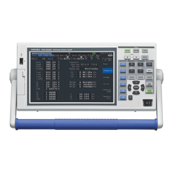
Hioki PW3390 Instruction Manual (248 pages)
Power Analyzer
Brand:
Hioki
| Category:
Measuring Instruments
| Size: 7 MB
Table of Contents
Table of Contents
3
Contents
9
Introduction
9
Confirming Package Contents
10
Safety Notes
12
Usage Notes
15
Chapter 1 Overview
19
Product Overview
19
Features
20
Operating Overview
22
Chapter 2 Names and Functions of Parts, Basic Operations & Screens
23
Names and Functions of Parts
23
Output Terminal
25
Basic Operations
26
Display Items and Screen Types
27
Common Display Items
27
Measurement Screen
28
Screen Types
29
Chapter 3 Measurement Preparations
33
Operations in General
33
Initial Instrument Preparations
34
Pre-Operation Inspection
36
Connecting the Power Cord
37
Grounding the Instrument's Functional Earth (When Measuring in Noisy Environments)
37
Connecting the Voltage Measurement Cables
38
Connecting the Current Sensors
38
Turning the Power on and off
41
Selecting the Wiring Mode
42
Setting the Current Sensors
46
Attaching to the Lines to be Measured and Zero Adjustment
49
Verifying Correct Wiring (Connection Check)
51
Chapter 4 Viewing Measurement Values
53
Measurement Value Display Procedure
53
Viewing Power Measurements, and Changing the Measurement Configuration
57
Displaying Power Measurements
57
Selecting Ranges
59
Selecting the Sync Source
64
Frequency Measurement Settings
66
Selecting the Rectification Method
68
Setting Scaling (When Using VT(PT) or CT)
69
Setting the Low-Pass Filter
70
Integration Value Observation
71
Displaying Integration Values
71
Setting the Integration Mode
74
Manual Integration Method
75
Integration Combined with Timing Control
77
Viewing Harmonic Measurement Values
80
Displaying the Harmonic Bar Graph
80
Displaying the Harmonic List
82
Displaying Harmonic Vectors
83
Selecting the Harmonic Sync Source
85
Selecting the THD Calculation Method
86
Viewing Waveforms
87
Displaying Waveforms
87
Resizing Waveforms
90
Viewing Noise Measurement Values (FFT Function)
91
Displaying Noise Voltage and Current
91
Setting the Sampling Frequency and Points
93
Setting the Minimum Noise Frequency
94
Measurement Channel and Window Function Settings
96
Viewing Efficiency and Loss Measurement Values
97
Displaying Efficiency and Loss
97
Selecting the Calculation Formula
98
Measurement Examples
99
Viewing Motor Measurement Values (Model PW3390-03 Only)
102
Motor Input Settings
104
Measuring Motor Electrical Angle
110
Detecting the Motor Rotation Direction
113
Chapter 5 Operating Functions
115
Timing Control Functions
115
Averaging Function
118
Data Hold and Peak Hold Functions
120
Data Hold Function
120
Peak Hold Function
121
X-Y Plot Function
123
Delta Star Transform Function
124
Selecting the Calculation Method
126
Trend Function
127
Chapter 6 Changing System Settings
135
Initializing the Instrument (System Reset)
138
Factory Default Settings
139
Chapter 7 Data Saving and File Operations
141
Inserting and Removing Storage Media
142
The File Operation Screen
144
Media Formatting
145
Saving Operations
146
Measurement Data Saving
147
Manually Saving Measurement Data
147
Auto-Saving Measurement Data
149
Selecting Measurement Items to Save
151
Saving Noise Data and Waveform Data
153
Saving Noise Data
153
Saving Wave Data
154
Saving Screen Capture Images
155
Loading Screenshots
156
Saving Setting Configurations
157
Reloading Setting Configurations
158
File and Folder Operations
159
Creating Folders
159
Copying Files and Folders
160
Deleting Files and Folders
162
Renaming Files and Folders
163
Chapter 8 Connecting External Devices
165
Connecting Multiple PW3390 (Synchronized Measurements)
165
Controlling Integration with External Signals
169
Using Analog and Waveform D/A Output
172
Connecting Application-Specific Devices to the Instrument
172
Output Item Selection
174
Output Level
177
D/A Output Examples
178
Connecting the Instrument to a LR8410 Link-Compatible Logger
180
Configuring and Connecting the Adapter
181
Using the Motor Testing
182
Chapter 9 Operation with a Computer
185
Control and Measurement Via Ethernet ("LAN") Interface
186
LAN Settings and Network Environment Configuration
186
Instrument Connection
188
Remote Control of the Instrument by Internet Browser
190
Connecting to the Instrument
190
Operating Procedure
191
Control and Measurement Via USB Interface
192
Connecting to the Instrument
192
After Connecting
192
Control and Measurement Via RS-232C Interface
193
Connecting to the Instrument
193
Setting the RS-232C Communications Speed
194
Chapter 10 Specifications
197
General Specifications
197
Basic Specifications
198
Functions Specifications
207
Setting Specifications
212
Measurement Item Details
215
Calculation Formula Specifications
218
Wiring System Diagram Specifications
225
Chapter 11 Maintenance and Service
227
Cleaning
227
Trouble Shooting
227
Error Indication
230
Disposing of the Instrument
234
Appendix 1 6
235
Appendix
235
Appendix 1Block Diagram
235
Appendix 2Measurement Data Saving Format
236
Appendix 3Physical Illustration
239
Appendix 4Rack Mounting
240
Index
241
Advertisement
Hioki PW3390 Instruction Manual (108 pages)
Power Analyzer
Brand:
Hioki
| Category:
Measuring Instruments
| Size: 1 MB
Table of Contents
Table of Contents
2
1 Communication Command Overview
6
Commands/Messages
6
Command Syntax
7
Command Program Header
7
Query Program Header
8
Response Message
8
Terminator and Separator
9
Multiple-Command Header Omission
10
Note
10
2 Command Reference (Standard Command)
11
Clear Standard Event Status Register (SESR) (Except Output Queue)
11
Read Standard Event Status Register (SESR)
11
Query Device ID (Recognition Code)
12
Set 1 for Output Queue When Finished All Pending Operations
12
Query Instrument Options
13
Initialize Instrument
13
Request a Sampling
13
Execute Next Command after Command Has Finished Processing
14
3 Command Reference (Device-Specific Commands)
15
Set and Query Frequency Full Scale
15
Set and Query Coefficient of Integrated Full Scale
15
Set and Query D/A Output Items
16
Select and Query Waveform Output
16
Setting and Querying Full-Scale D/A Output Waveform
17
Select and Query Auto Range Limit
17
Set and Query Average
18
Set and Query LCD Backlight
18
Select and Query Beep Sound
19
Set and Query Efficiency, Pin of Loss Calculation Formula
19
Set and Query Efficiency, Pout of Loss Calculation Formula
20
Set and Query Automatic Saving
20
Query Existence of CF Card
21
Acquire File Name in CF Card
21
Acquire Folder Name in CF Card
22
Acquire File Data in CF Card
23
Querying File Size in CF Card
24
Set and Query Time
25
Set and Query Current Auto Range
26
Setting and Querying Phase Correction Formulas for Current Sensors
26
Set and Query Phase Correction Angle for Current Sensors
27
Set and Query Phase Correction Frequency for Current Sensors
27
Select and Query Current Rectifier Type
28
Set and Query Current Range
29
Set and Query Current Sensor for CT9920
30
Initialize Data of Saved Items
30
Set and Query Efficiency, Saved Items of Loss Calculation Value
31
Set and Query Saved Items of Motor Input
31
Initialize Harmonic Saved Data Items
32
Select and Query Harmonic List Saved Items
33
Set and Query Output Order of Harmonic Data Saving
34
Set and Query Saved Items of Integration Values
35
Set and Query Noise Peak Value Saving
36
Set and Query Saved Items of Normal Measurement Values in Respective Channels
37
Set and Query Saved Items of Sum's Normal Measurement Values
38
Set and Query Saved Items of Voltage Data
39
Set and Query Saved Items of Current Data
40
Select and Query ON/OFF of Δ-Y Calculation
41
Execute and Query Zero Adjust
42
Key Operations of the Instrument
43
Switching Display
43
Setting and Querying Display Items of Select Screens
44
Select and Query Display Screen Color
44
Select and Query Start up Screen
45
Set and Query Motor Analysis Function Phase Zero Adjust Degree
45
Select and Query Motor Analysis Function Channel a Input
46
Set and Query Motor Analysis Function Channel a Input Frequency Range
47
Set and Query Motor Analysis Function Channel a Rating Torque
48
Select and Query Low-Pass Filter of Motor Analysis Function
48
Execute and Clear Motor Analysis Function's Phase Zero Adjust
49
Set and Query Motor Analysis Function Channel a Range
49
Set and Query Motor Analysis Function Channel a Scaling
50
Set and Query Input Frequency Source for Motor Analysis Function's Slip Calculation
50
Set and Query Motor Analysis Function's Motor Synchronized Sources
51
Select and Query Motor Analysis Function Channel a Unit
51
Execute Zero Adjust of Motor Analysis Function
52
Set and Query Motor Analysis Function Channel B Range
52
Set and Query Pulse ON/OFF of Motor Analysis Function Channel B Input
53
Set and Query Motor Analysis Function Channel Z Input
53
Set and Query Motor Analysis Function Channel B Measured Maximum Frequency
54
Set and Query Motor Analysis Function Motor Pole Value
54
Set and Query Pulse Values of Motor Analysis Function Channel B
55
Set and Query Motor Analysis Function Channel B Scaling
55
Select and Query Motor Analysis Function Channel B Units
56
Select and Query Noise Analysis Measurement Channel
56
Set and Query Noise Lower Limit Frequency
57
Select and Query Noise Analysis Point Values
57
Select and Query Noise Analysis Sampling Speed
58
Set and Query Noise Analysis Window Function
58
Set and Query Zero Cross Filter
59
Set and Query Measurement Lower Limit Frequency
59
Select and Query Frequency Measurement Source
60
Select and Query Harmonic Synchronized Source
60
Set and Query THD Calculation Formula
61
Set and Query Header for Response Message
61
Set and Query Hold Status
62
Set and Query Integration Mode
63
Execute Integration Data Reset
63
Execute Integration (Time) Start
64
Query Integration (Time)
64
Execute Integration (Time) Stop
64
Set and Query Interval Time
65
Set and Query IP Address
65
Set and Query Default Gateway
66
Set and Query Subnet Mask
66
Set and Query Key Lock
67
Set and Query Main Instrument Display Language
67
Select and Query Low Pulse Filter (LPF)
68
Query Measurement Data
69
Query Harmonic Measurement Data
70
Query Noise Measurement Value Data
71
Query Voltage Noise Measurement Value Data
71
Query Current Noise Measurement Value Data
72
Initialize Communication Output Item Data
72
Set and Query Efficiency, Loss Calculation Value Communication Output Items
73
Set and Query Communication Output Items of Motor Input
74
Initialize Harmonic Communication Output Data Items
74
Select and Query Harmonic List Communication Output Items
75
Set and Query Output Order of Harmonic Data Communication Output
76
Set and Query Communication Output Items of Integration Value
77
Set and Query Normal Measurement Value Communication Output Items of Respective Channels
78
Set and Query Sum's Normal Measurement Value Communication Output Items
79
Set and Query Voltage Data Communication Output Items
80
Set and Query Current Data Communication Output Items
81
Query Existence of USB Memory
82
Acquire File Name in USB Memory
82
Acquire Folder Name in USB Memory
83
Acquire File Data in USB Memory
83
Querying File Size in USB Memory
84
Select and Query Wiring Mode
85
Setting and Querying Formula for Three-Phase Power
86
Set and Query Execution Confirmation Message
86
Select and Query RS232C Communication Speed
87
Set and Query Automatic Saving Folder Name
87
Set and Query Manual Saving Folder Name
88
Select and Query Manual Saving Media Location
88
Setting and Querying Delimiter for CSV File
89
Set and Query CT Ratio
89
Set and Query VT Ratio
90
Set and Query Synchronized Source
90
Select and Query Actual Time ON/OFF
91
Set and Query Actual Time Start Time
92
Set and Query Actual Time Stop Time
93
Select and Query Master/Slave of Synchronized Control Master
94
Set and Query Synchronized Event Items
94
Set and Query Timer Control ON/OFF
95
Set and Query Timer
95
Set and Query Numerical Data Format
96
Set and Query Response Message Unit Separator
97
Set and Query Voltage Auto Range
98
Select and Query Voltage Rectifier Type
99
Set and Query Voltage Range
100
Set and Query Zero Suppress
101
4 Fundamental Measurement Item Parameters
102
5 Troubleshooting
107
Hioki PW3390 Firmware Update Procedures (2 pages)
Brand:
Hioki
| Category:
Measuring Instruments
| Size: 0 MB
Table of Contents
Firmware Update File Preparation
1
Inserting the Update Medium
1
File List Display
1
Initiating the Update
2
Update Confirmation
2
Completing the Update
2
Version Confirmation
2
Advertisement
Hioki PW3390 Measurement Manual (2 pages)
Power Analyzer
Brand:
Hioki
| Category:
Measuring Instruments
| Size: 0 MB
Table of Contents
Connect the Cables and Sensors, and Power on
1
Select the Wiring Mode
2
Select the Current Sensors
2
Execute Quick Setup, and Verify Correct Wiring
2
View Measurement
2
Advertisement
Related Products
Hioki PW3390-01
Hioki PW3390-02
Hioki PW3390-03
Hioki PW3335
Hioki PW3365-20
Hioki PW3336-03
Hioki PW3336-02
Hioki PW3337-01
Hioki PW3337-03
Hioki PW3365
Hioki Categories
Measuring Instruments
Test Equipment
Data Loggers
Multimeter
Accessories
More Hioki Manuals
Login
Sign In
OR
Sign in with Facebook
Sign in with Google
Upload manual
Upload from disk
Upload from URL