Sign In
Upload
Manuals
Brands
HIMA Manuals
Control Unit
HIMax X-HART 32 01
User Manuals: HIMA HIMax X-HART 32 01 Safety Controller
Manuals and User Guides for HIMA HIMax X-HART 32 01 Safety Controller. We have
1
HIMA HIMax X-HART 32 01 Safety Controller manual available for free PDF download: Manual
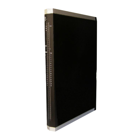
HIMA HIMax X-HART 32 01 Manual (58 pages)
HART Communication Module
Brand:
HIMA
| Category:
Control Unit
| Size: 1 MB
Table of Contents
Table of Contents
3
Introduction
5
Structure and Use of the Manual
5
Table 1: Additional Valid Manuals
5
Target Audience
5
Formatting Conventions
6
Safety Notes
6
Operating Tips
7
2 Safety
8
Intended Use
8
Environmental Requirements
8
ESD Protective Measures
8
Table 2: Environmental Requirements
8
Residual Risk
9
Safety Precautions
9
Emergency Information
9
3 Product Description
10
Safety Function
10
Reaction in the Event of a Fault
10
Scope of Delivery
10
Type Label
11
Figure 1: Sample Type Label
11
Structure
12
Block Diagram
12
Figure 2: Block Diagram
12
Indicators
13
Figure 3: Indicators
13
Module Status Indicators
14
Table 3: Blinking Frequencies of Leds
14
Table 4: Module Status Indicators
14
System Bus Indicators
15
I/O Indicators
15
Table 5: System Bus Indicators
15
Table 6: I/O Indicators Leds
15
Product Data
16
Figure 4: Views
16
Table 7: Product Data
16
Table 8: Specifications for the HART Channels
17
Connector Boards
18
Mechanical Coding of Connector Boards
18
Table 9: Available Connector Boards
18
Coding of X-CB 016 and X-CB 017 Connector Boards
19
Table 10: Position of Coding Wedges on HART Module Slot
19
Connector Boards for Analog Input Modules
20
Table 11: Terminal Assignment for Connector Boards with Screw Terminals
22
Table 12: Cable Plug Properties
22
Table 13: Pin Assignment for the System Cable Plug
24
Connector Board for Analog Output Modules
25
Figure 8: Connector Boards with Screw Terminals
25
Table 14: Terminal Assignment for Mono Connector Boards with Screw Terminals
26
Table 15: Cable Plug Properties
26
Table 16: Terminal Assignment for Redundant Connector Boards with Screw Terminals
27
Table 17: Cable Plug Properties
27
Table 18: Pin Assignment for Mono Connector Boards with Cable Plug
29
Table 19: Pin Assignment for Redundant Connector Boards with Cable Plug
30
System Cable
31
System Cable X-CA 005
31
Cable Plug Coding
31
Figure 10: System Cable X-CA 001 01 N
31
System Cable X-CA 011
32
Cable Plug Coding
32
Figure 11: System Cable X-CA 011 01 N
32
Table 20: Cable Data
32
Table 21: Available System Cables
32
Table 22: Cable Data
32
Table 23: Available System Cables
32
4 Start-Up
33
Mounting
33
Wiring I/O Channels Not in Use
33
Mounting and Removing the Module
34
Mounting a Connector Board
34
Figure 12: Example of How to Insert the Mono Connector Board
34
Figure 13: Example of How to Secure the Mono Connector Board with Captive Screws
35
Mounting and Removing the Module
36
Figure 14: Mounting and Removing a Module
37
Configuring the Module in Silworx
38
Tab: Module
39
Table 24: Module Tab in the Hardware Editor
39
Tab: I/O Submodule HART_32_01
40
Table 25: Tab I/O Submodule HART_32_01 in the Hardware Editor
41
Tab: I/O Submodule HART_32_01: Channels
42
Submodule Status [DWORD]
42
Table 26: Tab I/O Submodule Hart_32_01:Channels in the Hardware Editor
42
Table 27: Submodule Status [DWORD]
42
Diagnostic Status [DWORD]
43
Table 28: Diagnostic Information [DWORD]
43
Connection Variants
44
HART Module with Analog Input Module
44
Figure 15: Connection of Analog Input Modules to the HART Module
44
HART Module with Redundant Analog Input Modulesn
45
Figure 16: Redundant Connection of Analog Input Modules to the HART Module
45
HART Module with Analog Output Module
46
Figure 17: Connection of Analog Output Modules to the HART Module
46
HART Module with Redundant Analog Output Modules
47
Figure 18: Redundant Connection of Analog Output Modules to the HART Module
47
5 Operation
48
Handling
48
Diagnosis
48
6 Maintenance
49
Maintenance Measures
49
Loading the Operating System
49
Proof Test
49
7 Decommissioning
50
8 Transport
51
9 Disposal
52
Appendix
54
Glossary
54
Index of Figures
55
Index of Tables
56
Index
57
Advertisement
Advertisement
Related Products
HIMA DIO 24/16 01
HIMA HIMatrix F1 DI 16 01
HIMA HIMatrix F2 DO 16 01
HIMA HIMatrix F2 DO 4 01
HIMA HIMatrix F2 DO 8 01
HIMA HIMatrix F20
HIMA HIMatrix F3
HIMA HIMatrix F3 AIO 8/4 01
HIMA HIMatrix F3 DIO 16/8 01
HIMA HIMatrix F3 DIO 20/8 01
HIMA Categories
Controller
Control Unit
I/O Systems
Industrial Equipment
Power distribution unit
More HIMA Manuals
Login
Sign In
OR
Sign in with Facebook
Sign in with Google
Upload manual
Upload from disk
Upload from URL