Sign In
Upload
Manuals
Brands
Hettich Manuals
Laboratory Equipment
MIKRO 22 R
Hettich MIKRO 22 R Manuals
Manuals and User Guides for Hettich MIKRO 22 R. We have
1
Hettich MIKRO 22 R manual available for free PDF download: Repair Instructions
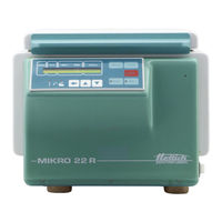
Hettich MIKRO 22 R Repair Instructions (51 pages)
Brand:
Hettich
| Category:
Laboratory Equipment
| Size: 1.02 MB
Table of Contents
Table of Contents
2
1 Introduction
6
2 Description of the New Hettich Centrifuges
7
Functional Structure of the Mikro 22 / 22 R
7
Control Panel (CP)
7
Supply Board (SB) A1
8
Frequency Converter (FC) A2
8
Special Features
9
Motor / Tacho System
9
Imbalance Switch
10
Interlocking
10
Cooling
10
Temperature Sensor B1 in the Centrifuge Chamber
10
Function of the Cooling Board (CB) A3
10
Fan
10
Offset Calibration
11
Protection
11
3 Requirements for Error Identification
12
Correct Power Supply
12
Functional Check
12
Procedure for Diagnosing Errors
12
4 Error Messages
13
Brief Description
13
Description and Elimination of Errors
15
5 Factory Setting
23
Control Panel
23
Procedure for Initialisation
23
Imbalance Mode
24
OFFSET Alignment
24
OFFSET Value
25
Procedure for Performing an OFFSET Alignment
25
Note for Temperature Sensor in Centrifuge Chamber
25
6 Function Retrievals / Settings
26
Acoustic Signal
26
Hours of Operation
26
Slippage of the Drive
27
Setting Display Contrast on Control Panel
27
7 Functional Check
28
Functional Check at Factory
28
8 Functional Test
30
Checking the Proper Working Order
30
Proper Working Order after Repairs
30
9 Assembling and Disassembling Components
30
Speed Sensor B3 (Speedometer)
33
Motor M1 / Vibration Damper
33
FC (Frequency Converter)
33
SB (Supply Board) A1
33
CB A3 (Cooling Board) Only MIKRO 22 R
33
A Speed Sensor (Speedometer) B3 X4 A1
33
CP (Control Panel) A4
34
EPROM at CP
34
CC (Control Cables)
34
LL (Y1) (Lid Locking)
34
BR R1 (Brake Resistor)
34
Radio Interference Suppression Filter Z1
34
Mains Choke Coil (L1)
34
Assembly and Disassembly
34
N Radio Interference Suppression Filter Z1 X5-Q1 A1
34
Short the Mains Choke Coil
35
Mains Switch Q1
35
O Mains Switch on / off Q1
35
Appliance Plug B4, Overvoltage Protection F1
36
Imbalance Switch S1
36
Temperature Sensor B1 in Centrifuge Chamber
36
Temperature Sensor B2 at Condenser
36
Fan M3
36
Compressor M2
36
P Appliance Plug Q Overvoltage Protection
36
R Imbalance Switch S1 X3 A1
36
T Temperature Sensor (Centrifuge Chamber) B1 X3 A3
36
U Temperature Sensor (Condenser) B2 X2 A3
36
Lid Spring
37
Hinge Block
37
Y Hinge Block
37
10 Speedometer-Code-Position of the Rotors
38
11 Circuit Diagrams
40
Mains Supply with Supply Board (SB) 230 V
40
Mains Supply with Supply Board (SB) 115 V
41
Circuit Diagram Supply Board (SB)
42
Connecting Diagram and Component Layout Supply Board (SB)
43
Signals at Control Cable (between CP-SB)
44
Block Diagram Control Panel (CP)
46
Connecting Diagram Control Board (CP)
46
Block Diagram and Signals at Frequency Converter (FC)
47
Connecting Diagram Frequency Converter (FC)
48
Circuit Diagram Cooling Board
49
Connecting Diagram and Component Layout Cooling Board
50
12 Technical Specifications
51
Advertisement
Advertisement
Related Products
Hettich MIKRO 120
Hettich MIKRO 200
Hettich MIKRO 200 R
Hettich MIKRO 220
Hettich MIKRO 185
Hettich MIKRO 22
Hettich MIKRO 220 R
Hettich BlueMax Mini 2
Hettich BlueMax Mini 6
Hettich BlueMax Mini Type 3
Hettich Categories
Laboratory Equipment
Indoor Furnishing
Door Opening System
DC Drives
Drill
More Hettich Manuals
Login
Sign In
OR
Sign in with Facebook
Sign in with Google
Upload manual
Upload from disk
Upload from URL