Sign In
Upload
Manuals
Brands
HALE Manuals
Water Pump
AP
HALE AP Manuals
Manuals and User Guides for HALE AP. We have
2
HALE AP manuals available for free PDF download: Technical Manual, Operation And Maintenance Manual
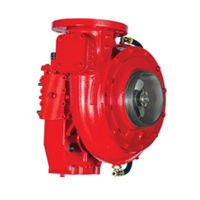
HALE AP Technical Manual (177 pages)
SINGLE STAGE BOOSTER PUMPS
Brand:
HALE
| Category:
Water Pump
| Size: 10.28 MB
Table of Contents
Table of Contents
3
1 Safety
13
Ppe
13
Environmental Protection
13
Training
14
Safety Summary
14
2 Introduction
19
Overview
19
How to Use this Manual
19
Pump Specifications and Numbering
20
Principles of Operation
20
Figure 1. Centrifugal Force from a Rotating Disk
20
Explanation of Terms
21
Atmospheric Pressure (Static Air Pressure)
21
Figure 2. Single Stage Water Flow
21
Cavitation
22
Dead Heading
22
Impeller and Clearance Rings
22
Priming Pump
22
Relief Valve
22
Figure 3. Clearance Ring Water Flow
22
PM Relief Valve Control
23
Volute
23
Standard Booster Pump Components
23
Figure 4. Parts of the Hale Booster Pump
23
Volute
24
Impeller and Shaft Assembly
24
Mechanical Seal
24
Figure 5. Mechanical Seal
24
Gearbox
25
Pump Drives
25
Optional Pump Components
26
Anodes
26
Figure 6. Direct Engine Mount
26
Figure 7. Hale Anode
26
Trvs
27
3 Maintenance Operating Procedures
29
Repair Verification Operations
30
Figure 8. Driver Compartment Indicator Lights
30
Figure 9. Pump Operator Panel
31
Vacuum Test
32
Table 1. Vacuum Test Tools and Consumables List
32
Pressure Test
34
Table 2. Pressure Test Tools and Consumables List
34
Pumping from Draft Verification Operations
35
Draft Limiting Factors
37
Table 3. Additional Losses Beyond NFPA Rating Baseline
37
Cavitation (Details)
38
Process of Cavitation
38
Figure 10. Results of Cavitation
38
Warning Signs of Cavitation
39
Discharge Pressure
39
Vacuum Compound Gauge
39
How to Prevent Cavitation
39
Figure 11. Low Pressure Regions
39
General Considerations
40
Table 4. Hose Sizes for Pump Rating Capacity
40
During Operations
41
Table 5. Lift Loss from Barometric Pressure
41
Post Operation Procedure
42
Table 6. Lift Loss from Elevation
42
4 Preventive Maintenance
43
Preventive Maintenance Plan and Schedule
43
Table 7. Recommended Preventive Maintenance - Pump
43
Table 8. Recommended Preventive Maintenance - Ancillary Equipment
44
Maintenance Log
45
Extreme Conditions Maintenance Guidelines
46
Freezing Weather
46
Contaminated Water
47
Booster Pump Preventive Maintenance Procedures
47
After each Use (Flush Pump)
47
Leakage Checks
47
Quarterly Maintenance
48
Check Gearbox Oil Level
48
Figure 12. Typical Gearbox Oil Fill/Level Component Locations
48
Perform Vacuum Test
49
Annual Pump Maintenance
50
Performance Testing
50
Testing Overview
50
Testing Equipment and Materials
50
Table 9. Example Performance Test
50
Table 10. Pressure and Flow for Various Size Nozzles
51
Performance Testing Test Procedure
53
Annual Pump Maintenance
53
Triennium Pump Maintenance
54
Gearbox Fluid Change
54
5 Corrective Maintenance (Repair)
55
Troubleshooting
55
PTO or Pump Engagement Problems
55
Table 11. Engagement SCR Table
55
Pump Priming Problems
56
Table 12. Pump Priming SCR Table
56
Insufficient Pump Capacity
57
Engine Speed Problems
57
Table 13. Insufficient Pump Capacity SCR Table
57
Table 14. Engine Speed SCR Table
57
Relief Valve Problems
58
Gearbox Problems
58
Discharge Valve Problems
58
Table 15. Relief Valve SCR Table
58
Table 16. Gearbox SCR Table
58
Table 17. Discharge Valve(S) SCR Table
58
Cavitation
59
Figure 13. Engine or Opposite Engine Rotation
59
Table 18. Cavitation SCR Table
59
Table 19. Rotation SCR Table
59
Maintenance Level 1
60
Maintenance Level 2
60
Maintenance Level 3
60
Maintenance Impeller Renew
60
Miscellaneous Maintenance
61
General Repair Guidelines
61
Match Mark or Note Component Orientation
61
Recommended Lubricants
61
Table 20. Recommended O-Ring Lubricant
61
Cleaning and Lubrication Required for Mechanical Seal Installation
62
Replacement Fasteners
62
Table 21. Recommended Mechanical Seal Lubricant
62
Table 22. Maximum Torque Values
62
Circlip/Snap Ring Installation
63
Thread Lock or Sealant Compound
63
Cleaning and Inspection Guidelines
63
Figure 14. Circlips (How to Recognize and Remove Them)
63
Recommended Cleaners
64
Repair Kits
64
Impeller Renew Kits
64
Worn Clearance Rings and Impeller Hubs
64
Figure 15. Measuring for Worn Clearance Rings and Impeller Hubs
65
Table 23. Impeller and Clearance Ring Diameters and Clearance Values
65
Removal and Replacement Instruction Guidelines
66
Tools Required/Suggested
66
General Pump Disassembly for Access Guidelines
67
Figure 16. Seal Removal Tool and Seal Driver Kit
67
Figure 17. Caliper (Depth Rod Extended)
67
General Pump Removal from the Apparatus
68
Table 24. Pump R&R from the Apparatus Tools and Consumables List
68
Figure 18. Pump and Gearbox Assembly R&R
69
General Pump Disassembly Methodology
70
Figure 19. One-Piece Volute (AP, CBP, MBP)
71
Figure 20. Three-Piece Volute (RSD)
71
Figure 21. AP Pump Exploded View
73
Figure 22. CBP Pump Exploded View
74
Figure 23. MBP Pump Exploded View
75
Figure 24. RSD Pump Exploded View
76
Figure 25. Gearbox Exploded View (All Except 3.74:1 GR)
77
Figure 26. Gearbox Exploded View (3.74:1 GR)
78
Level 1 Procedures
79
RSD Suction Head R&R
79
Table 25. RDS Suction Head R&R Tools and Consumables List
79
RSD Volute R&R
81
Table 26. RSD Volute R&R Tools and Consumables List
82
AP/MBP Volute R&R
84
Figure 27. AP/MBP Volute R&R
84
Table 27. AP Volute R&R Tools and Consumables List
84
CBP Volute R&R
86
Table 28. CBP Volute R&R Tools and Consumables List
86
MBP/RSD Inducer R&R
88
Figure 28. MBP Inducer R&R
89
Figure 29. RSD Inducer R&R
89
Table 29. MBP/RSD Inducer R&R Tools and Consumables List
90
MBP/RSD Impeller R&R
93
Figure 30. MBP Impeller R&R
94
Table 30. MBP/RSD Impeller R&R Tools and Consumables List
94
AP Impeller R&R
95
Figure 31. AP Impeller R&R
96
Table 31. AP Impeller R&R Tools and Consumables List
96
CBP Impeller R&R
99
Figure 32. CBP Impeller R&R
99
Table 32. CBP Impeller R&R Tools and Consumables List
100
Figure 33. NORD-Lock Washers Installation Details
101
AP/CBP/MBP Mechanical Seal R&R
102
Table 33. AP/CBP/MBP Mechanical Seal Bench Procedure Tools and Consumables List
102
Figure 34. Typical Mechanical Seal Detail
103
RSD Mechanical Seal R&R
105
Table 34. RSD Mechanical Seal Bench Procedure Tools and Consumables List
105
Figure 35. RSD Mechanical Seal Notch
106
Figure 36. Align Slot on Seal with Pin in Pump Head
107
AP/CBP/MBP Pump Head R&R
108
Table 35. AP/CBP/MBP Pump Head R&R Tools and Consumables List
109
RSD Pump Head R&R
110
Table 36. RSD Pump Head R&R Tools and Consumables List
111
Figure 37. Pump Head (Pump Side)
112
Figure 38. Pump Head (Drive Side)
113
Pump Head R&R Bench Procedures
114
Pump Shaft Oil Seal Bench Procedure
114
Table 37. Pump Shaft Oil Seal Bench Procedure Tools and Consumables List
114
RSD Mechanical Seal Anti Rotation Pin Bench Procedure
115
Table 38. Mechanical Seal Pin Bench Procedure Tools and Consumables List
116
Level 2 Procedures
117
Level 3 Procedures
117
Miscellaneous Procedures
118
Cooling System
118
Table 39. Gearbox Cooling Tube R&R Tools and Consumables List
119
Cooling Tube R&R
120
Pump Clearance Ring R&R
122
Table 40. Pump Clearance Ring R&R Tools and Consumables List
122
Figure 39. Slots Cut in Clearance Ring-Volute
123
Figure 40. Clearance Ring Driven Out-Volute
123
Figure 41. Wrap Around Clearance Rings - Pump Heads
125
Figure 42. Clearance Ring Drilled out (MPB Pump Head)
125
Figure 43. Clearance Ring Bent Inward and Cut Thru
125
Figure 44. Slots Cut in Clearance Ring - Suction Head
127
Figure 45. Clearance Ring Driven out - Suction Head
127
Figure 46. RSD Wrap Around Clearance Rings
128
General Install on the Apparatus
129
Figure 47. RSD Wrap Around Clearance Ring R & R
129
Gearbox
130
Gearbox R&R
130
Gearbox Bench Procedures
132
Input Shaft
133
Table 41. Input Shaft Bench Procedure Tools and Consumables List
133
Input Shaft Oil Seal (ONLY)
138
Table 42. Input Shaft Oil Seal Bench Procedure Tools and Consumables List
138
Input Shaft Bearings (ONLY)
139
Input Shaft Endcap (ONLY)
140
Table 43. Input Shaft Endcap Bench Procedure Tools and Consumables List
140
Drive Gear (Input Shaft)
141
Table 44. Drive Gear Bench Procedure Tools and Consumables List
142
Pump Shaft
143
Table 45. Pump Shaft Bench Procedure Tools and Consumables List
143
Figure 48. Pump Shaft Assembly
145
Figure 49. AP/CBP Pump Shaft
147
Figure 50. MBP/RSD Pump Shaft
148
Pump Shaft Bearings (ONLY)
151
Pump Shaft Endcap (ONLY)
151
Table 46. Pump Shaft Endcap R&R Tools and Consumables List
151
Pump Gear (ONLY)
153
Table 47. Pump Gear Bench Procedure Tools and Consumables List
154
Appendix A. Tightening (Torque) Information
159
Appendix B. Test Equipment and Special Tool Information
161
Special Tool Information
161
Appendix C. Ancillary Pump Equipment
163
Priming Systems
163
Priming Pump
163
Figure 51. Rotary Vane Positive Displacement Type Priming Pump
163
C.1. Priming Systems
163
Priming Valves
164
Figure 52. Rotor and Vanes
164
Figure 53. ESP Priming Pump
164
C.1.2 Priming Valves
164
Figure 54. PVG Priming Valve
165
Figure 55. SPVR Priming Valve
165
Temperature Control Devices
166
Trv
166
TRV-L Kit
166
Ancillary Equipment Preventive Maintenance Procedures
167
Weekly Maintenance
167
Pump Shift Warning Indicator Lights
167
Check Valves
167
Check and Clean Intake Strainers
167
Check All Gauges
167
Check Pump Controls
167
Inspect Water and Foam Tanks
167
Check Roof and Bumper Turrets
167
Check Auxiliary Fire Suppression Equipment
168
Monthly Maintenance
168
Priming System Test (Dry Vacuum Test
168
Drive Line and Flange Bolts
169
Figure 59. Grade 8 Bolt Marking
169
Figure 60. Class 10.9 Bolt Marking
169
Annual Maintenance
170
Check Drain Lines to Multi-Drain
170
Tank to Pump Flow Rate Test
170
C.3.3 Annual Maintenance
170
ESP Primer Maintenance
171
Figure 61. ESP Exploded View
171
Figure 62. ESP-PVG Primer Repair Kit (P/N 546-1410-03-0
172
Appendix D. Operator Maintenance Log
175
Appendix E. Manufacturer's Information
177
Manufacturer's Information
177
Warranty
177
Returned Goods Procedure
177
E.1. Manufacturer's Information
177
Advertisement
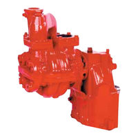
HALE AP Operation And Maintenance Manual (70 pages)
Booster Pumps
Brand:
HALE
| Category:
Water Pump
| Size: 4.61 MB
Table of Contents
Table of Contents
2
Section I: Introduction
5
Overview
5
Principals of Operation
5
Centrifugal Force
5
Pump Stages
6
Two-Stage Booster Pump
7
Components of a Booster Pump
7
Pump Body
7
Impeller and Shaft Assembly
7
Mechanical Seal
7
Gearbox
7
Pump Drives
8
Accessories
9
Auxiliary Cooling (Overheat Protection
9
Priming Systems
9
Priming the Pump
9
Priming Valves
10
Pressure Control
10
Thermal Relief Valveb (TRV
11
Anodes
11
Explanation of Terms
12
Section II Operating Procedures
13
Stationary Pumping Operations
13
Pumping from a Hydrant (General Operation)
13
Draft Limiting Factors
14
Pumping from Draft
14
Pump and Roll Operation
16
Relief Valve Procedures
16
TPM /P35 Relief Valve Procedures
16
Process of Cavitation
17
Warning Signs of Cavitation: Discharge and Gauges
18
Discharge Pressure
18
Vacuum Compound Gauge
18
How to Prevent Cavitation
18
During Operations
18
Preventive Measures
18
Post Operation Procedure
20
Section III Preventive Maintenance
21
Overview
21
Post-Operation Maintenance Procedures
21
Weekly Maintenance
21
Relief Valve Testing
21
Valve Maintenance
22
Verify All Gauges Are in Working Order
22
Inspect Water and Foam Tanks
22
Monthly Maintenance
23
Gearbox Lubrication
23
Priming System Test (Dry Vacuum Test) (Refer to NFPA 1901 or NFPA 1911)
23
Annual Pump Maintenance
24
Replace Gearbox Oil
24
Tank to Pump Flow Rate Test
24
Performance Testing Overview
25
Worn Clearance Rings and Impeller Hubs
28
Extreme Conditions Maintenance Guidelines
28
Section IV: Troubleshooting
29
Section V Maintenance and Repair
37
Overview
37
General Repair Guidelines
37
Cleaning and Inspection Guidelines
37
Recommended Cleaners
39
Pump Components
39
Pump and Gearbox Assembly
39
Remove the Pump from the Apparatus
39
AP Pump Disassembly
41
AP Pump Body
41
Remove AP Pump Body
41
Install the Pump Body
41
Ap Impeller and Mechanical Seal
41
Remove AP Impeller
41
Remove AP Mechanical Seal
42
Reinstall AP Mechanical Seal
42
Reinstall the AP Impeller
42
Remove Ap Pump Head
42
Reinstall Ap Pump Head
43
AP Gearbox
44
Disassemble AP Gearbox
44
Reassemble and Reinstall AP Gearbox
44
CBP Pump Repair
47
CBP Pump Body
47
Remove CBP Pump Body
47
Reinstall CBP Pump Body
47
Cbp Impeller and Mechanical Seal
47
Remove CBP Impeller
47
Reinstall CBP Impeller
48
Remove Cbp Mechanical Seal
48
Reinstall CBP Mechanical Seal
48
Cbp Pump Head
48
Remove Cbp Pump Head
48
Reinstall CBP Pump Head
49
Cbp Gearbox
49
Remove and Disassemble CBP Gearbox
49
Reassemble and Reinstall CBP Gearbox
50
2CBP Pump Repair
52
Disassemble the 2CBP Pump from the Gearbox Assembly
52
Reassemble Pump to Gearbox
52
Disassemble the 2CBP Gearbox
54
Reassemble and Reinstall 2CBP Gearbox
55
Section VI: Parts Lists
57
AP Pump
59
CBP Pump
62
2CBP Pump
66
Hydraulic Adapter
68
Tachometer Option
69
Advertisement
Related Products
HALE 2CBP
HALE CBP
HALE DSD
HALE FOAM MASTER 3.0
HALE FOAM MASTER 3.3
HALE FOAM MASTER 5.0
HALE FoamLogix 3.3
HALE FoamLogix 5.0
HALE Godiva KP1
HALE Categories
Water Pump
Recording Equipment
Control Systems
Industrial Electrical
Indoor Furnishing
More HALE Manuals
Login
Sign In
OR
Sign in with Facebook
Sign in with Google
Upload manual
Upload from disk
Upload from URL