Sign In
Upload
Manuals
Brands
H3C Manuals
Switch
S5560X-34S-EI
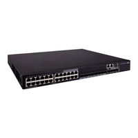
H3C S5560X-34S-EI Manuals
Manuals and User Guides for H3C S5560X-34S-EI. We have
2
H3C S5560X-34S-EI manuals available for free PDF download: Installation Manual
H3C S5560X-34S-EI Installation Manual (89 pages)
Brand:
H3C
| Category:
Switch
| Size: 6.21 MB
Table of Contents
Table of Contents
6
Preparing for Installation
8
Safety Recommendations
8
Examining the Installation Site
9
Temperature/Humidity
9
Cleanliness
9
Emi
10
Laser Safety
10
Installation Tools
10
Installing the Switch
11
Installing the Switch in a 19-Inch Rack
13
Installation Methods
13
Installation Accessories
14
Rack-Mounting the Switch by Using Front Mounting Brackets
15
S5560X-30F-EI, S5560X-54F-EI, S5560X-34S-EI, and S5560X-54S-EI Switches)
15
S5560X-54C-Pwr-Ei)
17
Mounting the Switch on a Workbench
20
Grounding the Switch
20
Grounding the Switch with a Grounding Strip
20
Grounding the Switch with a Grounding Conductor Buried in the Earth Ground
22
Installing/Removing a Fan Tray
23
Installing a Fan Tray
24
Removing a Fan Tray
24
Installing/Removing a Power Module
25
Installing a PSR150-A1/PSR150-A2/PSR150-D1 Power Module
26
Removing a PSR150-A1/PSR150-A2/PSR150-D1 Power Module
27
Installing a PSR360-56A/PSR560-56D/PSR720-56A/PSR1110-56A Power Module
27
Removing a PSR360-56A/PSR560-56D/PSR720-56A/ PSR1110-56A Power Module
29
Connecting the Power Cord
30
Connecting the Power Cord for the Built-In AC Power Module
31
Connecting a Power Cord for the Built-In DC Power Module
31
Connecting the PSR150-A1/PSR150-A2
32
Connecting the PSR150-D1/PSR560-56D
33
Connecting the PSR360-56A/PSR720-56A/PSR1110-56A
34
Installing/Removing an Expansion Card
35
Installing an Expansion Card
35
Removing an Expansion Card
38
Verifying the Installation
38
Accessing the Switch for the First Time
39
Setting up the Configuration Environment
39
Connecting the Serial Console Cable
39
Connecting the Micro USB Console Cable
40
Setting Terminal Parameters
42
Powering on the Switch
42
Setting up an IRF Fabric
44
IRF Fabric Setup Flowchart
44
Planning IRF Fabric Setup
45
Planning IRF Fabric Size and the Installation Site
45
Identifying the Master Switch and Planning IRF Member Ids
45
Planning IRF Topology and Connections
46
Identifying Physical IRF Ports on the Member Switches
47
Planning the Cabling Scheme
47
Configuring Basic IRF Settings
49
Connecting the Physical IRF Ports
49
Verifying the IRF Fabric Setup
50
Maintenance and Troubleshooting
51
Fixed Power Module Failure
51
Hot-Swappable Power Module Failure
52
Fixed Fan Tray Failure
53
Hot-Swappable Fan Tray Failure
53
Configuration Terminal Display Problems
53
No Display
53
Garbled Display
53
Appendix A Chassis Views and Technical Specifications
55
Chassis Views
55
S5560X-30C-Ei
55
S5560X-30C-Pwr-Ei
56
S5560X-54C-Ei
57
S5560X-54C-Pwr-Ei
58
S5560X-30F-Ei
59
S5560X-54F-Ei
60
S5560X-34S-Ei
61
S5560X-54S-Ei
62
Technical Specifications
62
Appendix B Frus and Compatibility Matrixes
67
Hot-Swappable Power Modules
68
Hot-Swappable Fan Trays
69
Expansion Cards
69
Connecting Cables to the Copper Ports on the Interface Cards
71
Appendix C Ports and Leds
73
Ports
73
Console Port
73
Management Ethernet Port
73
USB Port
73
1/10BASE-T Autosensing Ethernet Port
74
5G/2.5G/1000BASE-T Autosensing Ethernet Port
74
10G/5G/2.5G/1000BASE-T Autosensing Ethernet Port
75
SFP Port
75
SFP+ Port
77
SFP28 Port
79
QSFP+ Port
80
Combo Interface
82
Leds
82
System Status LED
82
Power Module Status LED
82
RPS Status LED
83
Mode Led
83
10/100/1000BASE-T Autosensing Ethernet Port LED
83
SFP Port LED
84
SFP+ Port LED
85
QSFP+ Port LED
85
Management Ethernet Port LED
86
Expansion Card Status LED
86
Port Status LED on the Expansion Card
87
Input Status LED and Output Status LED on the Power Module
87
Fan Tray Status LED on the Fan Tray
87
Appendix D Cooling System
88
Advertisement
H3C S5560X-34S-EI Installation Manual (55 pages)
Brand:
H3C
| Category:
Switch
| Size: 5.73 MB
Table of Contents
Table of Contents
1
Preparing for Installation
3
Safety Recommendations
3
Examining the Installation Site
3
Temperature/Humidity
4
Cleanliness
4
Corrosive Gas Limit
4
Emi
5
Laser Safety
6
Installation Tools
6
Installing the Switch
7
Installing the Switch in a 19-Inch Rack
9
Installation Methods
9
Installation Accessories
10
Rack-Mounting the Switch by Using Front Mounting Brackets
11
Rack-Mounting the Switch by Using Front and Rear Mounting Brackets
12
Mounting the Switch on a Workbench
16
Grounding the Switch
16
Grounding the Switch with a Grounding Strip
16
Grounding the Switch with a Grounding Conductor Buried in the Earth Ground
18
Installing/Removing a Fan Tray
19
Installing a Fan Tray
20
Removing a Fan Tray
20
Installing/Removing a Power Module
21
Installing a PSR150-A1/PSR150-A2/PSR150-D1 Power Module
22
Removing a PSR150-A1/PSR150-A2/PSR150-D1 Power Module
23
Removing a PSR360-56A/PSR560-56D/PSR720-56A/ PSR1110-56A Power Module
25
Connecting the Power Cord
26
Connecting the Power Cord for the Built-In AC Power Module (1)
27
Connecting the Power Cord for the Built-In AC Power Module (2)
27
Connecting a Power Cord for the Built-In DC Power Module
29
Connecting the PSR150-A1/PSR150-A2
29
Connecting the PSR150-D1/PSR560-56D
30
Connecting the PSR360-56A/PSR720-56A/PSR1110-56A
31
Installing/Removing an Expansion Card
32
Installing an Expansion Card
32
Removing an Expansion Card
35
Verifying the Installation
35
Accessing the Switch for the First Time
36
Connecting the Switch to a Configuration Terminal
36
Connecting a DB9-To-RJ45 Console Cable
37
Connecting a USB-To-RJ45 Console Cable
38
Connecting a Micro USB Console Cable
40
Setting Terminal Parameters
42
Powering on the Switch
42
Setting up an IRF Fabric
44
IRF Fabric Setup Flowchart
44
Planning IRF Fabric Setup
45
Planning IRF Fabric Size and the Installation Site
45
Identifying the Master Switch and Planning IRF Member Ids
45
Planning IRF Topology and Connections
46
Identifying Physical IRF Ports on the Member Switches
47
Planning the Cabling Scheme
47
Configuring Basic IRF Settings
50
Connecting the Physical IRF Ports
50
Verifying the IRF Fabric Setup
51
Maintenance and Troubleshooting
52
Fixed Power Module Failure
52
AC Input Failure
52
DC Input Failure
52
AC and DC Concurrent Input Failure
53
Removable Power Module Failure
54
Fixed Fan Tray Failure
54
Removable Fan Tray Failure
54
Configuration Terminal Display Problems
55
No Display
55
Garbled Display
55
Advertisement
Related Products
H3C S5560X-30C-EI
H3C S5560X-30C-PWR-EI
H3C S5560X-30F-EI
H3C S5560X-30F-EIF
H3C S5560X-34C-HI
H3C S5560X-30F-HI
H3C S5560X-54S-EI
H3C S5560X-HI Series
H3C S5560X-54F-HI
H3C S5560X-54C-PWR-EI
H3C Categories
Switch
Network Router
Wireless Access Point
Control Unit
Gateway
More H3C Manuals
Login
Sign In
OR
Sign in with Facebook
Sign in with Google
Upload manual
Upload from disk
Upload from URL