Sign In
Upload
Manuals
Brands
Guardian Manuals
Portable Generator
5240
Guardian 5240 Manuals
Manuals and User Guides for Guardian 5240. We have
2
Guardian 5240 manuals available for free PDF download: Diagnostic Repair Manual, Installation And Owner's Manual
Guardian 5240 Diagnostic Repair Manual (151 pages)
Brand:
Guardian
| Category:
Portable Generator
| Size: 5.81 MB
Table of Contents
Electrical Formulas
2
Table of Contents
3
Specifications
6
Generator
6
Stator Winding Resistance Values/Rotor Resistance
6
Engine
7
Fuel Consumption
7
Mounting Dimensions
8
Major Features
10
Part 1 - General Information
11
Generator Identification
12
Air-Cooled, Prepackaged
12
Prepackaged Installation Basics
13
Introduction
13
Selecting a Location
13
Grounding the Generator
13
The Fuel Supply
13
The Transfer Switch / Load Center
13
Power Source and Load Lines
15
System Control Interconnections
15
Preparation before Use
16
General
16
Fuel Requirements
16
Fuel Consumption
16
Reconfiguring the Fuel System
16
Engine Oil Recommendations
18
Testing, Cleaning and Drying
19
Meters
19
The vom
19
Measuring AC Voltage
19
Measuring DC Voltage
19
Measuring AC Frequency
19
Measuring Current
20
Measuring Resistance
20
Electrical Units
21
Ohm's Law
21
Visual Inspection
22
Insulation Resistance
22
The Megohmmeter
22
Stator Insulation Resistance Test
23
Rotor Insulation Resistance Test
24
Cleaning the Generator
24
Drying the Generator
24
Engine-Generator Protective Devices
25
General
25
Low Battery
25
Low Oil Pressure Shutdown
25
High Temperature Switch
25
Overspeed Shutdown
25
RPM Sensor Failure
25
Overcrank Shutdown
26
Operating Instructions
27
Control Panel
27
To Select Automatic Operation
28
Manual Transfer to "Standby" and Manual Startup
28
Manual Shutdown and Retransfer
29
Back to "Utility
29
Automatic Operating Parameters
30
Introduction
30
Automatic Operating Sequences
30
Part 2 - Ac Generators
31
Description and Components
32
Introduction
32
Engine-Generator Drive System
32
The AC Generator
32
Rotor Assembly
32
Stator Assembly
33
Brush Holder and Brushes
33
Other AC Generator Components
33
Operational Analysis
35
Rotor Residual Magnetism
35
Field Boost
35
Operation
36
Troubleshooting Flowcharts
37
Voltage or Residual Voltage
37
Problem 2 - Generator Produces Low Voltage at No-Load
39
High Voltage at No-Load
39
Low Voltage at No-Load
39
Problem 4 - Voltage and Frequency Drop Excessively When Loads Are Applied
40
Excessively When Loads Are Applied
40
Diagnostic Tests
41
Introduction
41
Safety
41
Test 1- Check Main Circuit Breaker
41
Test 2- Check Ac Output Voltage
41
Test 4 - Fixed Excitation Test/Rotor
42
Amp Draw Test
42
Test 5: Wire Continuity
43
Test 6 - Check Field Boost
44
Test 7 - Testing the Stator with a vom
44
Test 8 - Resistance Check of Rotor Circuit
46
Test 9 - Check Brushes and Slip Rings
46
Test 10 - Test Rotor Assembly
47
Test 11 - Check AC Output Frequency
47
Test 12 - Check and Adjust Engine Governor (Single Cylinder Units)
48
Test 12A - Check Stepper Motor Control
48
(V-Twin Engine Units)
48
Test 13 - Check and Adjust
48
Voltage Regulator
50
Test 14 - Check Voltage and Frequency under Load
50
Test 15 - Check for Overload Condition
50
Test 16 - Check Engine Condition
50
Part 3 - "V-Type Prepackaged Transfer Switches
51
Transfer Switches
51
Description and Components
52
General
52
Enclosure
52
Transfer Mechanism
53
Transfer Relay
53
Neutral Lug
54
Manual Transfer Handle
54
Terminal Block
54
Fuse Holder
55
Operational Analysis
56
Utility Source Voltage Available
58
Utility Source Voltage Failure
59
Transfer to Standby
60
Transfer to Standby
61
Utility Restored
62
De-Energized
63
Utility Restored, Transfer Switch De-Energized
63
Retransfer Back to Utility
64
Utility Restored, Retransfer Back to Utility
64
Transfer Switch in Utility
65
Troubleshooting Flow Charts
66
Introduction to Troubleshooting
66
No Transfer to Standby
66
No Retransfer to Utility Power
67
Problem 7 - Blown F1 or F2 Fuse
67
Starts When Loss of Utility Occurs, Generator Shuts down When Utility Returns but There Is no Retransfer to Utility Power
67
Diagnostic Tests
68
General
68
Test 21 - Check Voltage at Terminal Lugs E1, E2
68
Test 22 - Check Voltage at Standby Closing Coil C2
68
Test 23 - Test Transfer Relay TR
69
Test 21 - Check Voltage at Terminal Lugs E1, E2
69
Test 22 - Check Voltage at Standby Closing Coil C2
69
Test 24- Check Manual Transfer
70
Switch Operation
70
Test 25- Test Limit Switch Xb1
71
Test 26 - Check 23 and
71
Wiring/Connections
71
Test 27- Check Voltage at Terminal Lugs N1, N2
72
Test 28 - Check Voltage at Utility
72
And Utility 2 Terminals
72
Test 29 - Check Voltage at Utility Closing Coil C1
72
Test 30 - Check Fuses F1 and F2
73
Test 28 - Check Voltage at Utility
73
Test 31 - Test Limit Switch Xa1
74
Test 32 - Continuity Test of Wiring (C1)
74
Test 33 - Continuity Test of Wiring (C2)
74
Test 34 - Check N1 and N2 Wiring
75
Test 35 - Check Transformer (Tx)
75
Part 4 - DC Control
77
Description and Components
78
General
78
Terminal Strip / Interconnection Terminal
78
Transformer (TX)
78
Circuit Board
78
AUTO-OFF-MANUAL Switch
82
15 Amp Fuse
82
Operational Analysis
84
Introduction
84
Utility Source Voltage Available
84
Initial Dropout of Utility Source Voltage
86
Engine Cranking
88
Engine Startup and Running
90
Initial Transfer to the "Standby" Source
92
Re-Transfer to Utility
94
Utility Voltage Restored / Re-Transfer to Utility
94
Engine Shutdown
96
Troubleshooting Flow Charts
98
When Utility Power Source Fails
98
When AUTO-OFF-MANUAL Switch Is Set to "MANUAL
98
Problem 10 - Engine Cranks but Won't Start
99
Problem 11 - Engine Starts Hard and Runs Rough / Lacks Power
100
Runs Rough / Lacks Power
100
Problem 12 - Engine Starts and Runs, then Shuts down
101
Then Shuts down
101
Problem 13 - no Battery Charge
102
Problem 14 - Unit Starts and Transfer Occurs When Utility Power Is Available
103
Immediately in Auto - no Transfer to Standby. Utility Voltage Is Present
103
When Utility Power Is Available
103
Problem 16 - 15 Amp Fuse (F1) Blown
104
Problem 17 - Generator will Not Exercise
104
Problem 18 - no Low Speed Exercise
104
Diagnostic Tests
105
Introduction
105
AUTO-OFF-MANUAL Switch
105
Test 42 - Try a Manual Start
105
Test 43- Test Auto-Off-Manual Switch
105
Test 44 - Check Wire 15/15A/15B/239/0
106
Voltage
106
Test 45 - Check 15 Amp Fuse
107
Test 46- Check Battery
107
Test 47 - Check Wire 56 Voltage
108
Test 48- Test Starter Contactor Relay
108
(V-Twin Only)
108
Test 49- Test Starter Contactor
108
Test 50 - Test Starter Motor
109
Test 51 - Check Fuel Supply
111
And Pressure
111
Test 52 - Check Circuit Board
112
Wire 14 Output
112
Test 53 - Check Fuel Solenoid
113
Test 54- Check Choke Solenoid
114
(V-Twins Units Only)
114
Test 55 - Check for Ignition Spark
115
Test 56 - Check Spark Plugs
116
Test 57- Check Engine / Cylinder Leak down Test / Compression Test
116
Test 58 - Check Shutdown Wire
117
Test 59 - Check and Adjust
118
Ignition Magnetos
118
Test 60- Check Oil Pressure Switch
119
And Wire 86
119
Test 61 - Check High Oil
120
Temperature Switch
120
Test 62 - Check and Adjust Valves
121
Test 63 - Check Fuel Regulator
121
(7 Kw Natural Gas Units Only)
121
Test 64 - Check Battery Charge Output
122
Test 65 - Check Transformer (TX)
122
Voltage Output
122
Battery Charger
123
Test 66 - Check AC Voltage at Battery Charger
123
Test 67 - Check Battery Charge Relay
124
Relay (BCR)
124
Test 68 - Check Battery Charge
124
Winding Harness
124
Test 69 - Check Battery Charger Wiring
125
Test 70 - Check Wire 18 Continuity
125
Test 71 - Check N1 and N2 Voltage
125
At the Circuit Board
126
Test 72 - Check Utility Sensing Voltage
126
Test 73 - Test Set Exercise Switch
126
Test 75 - Check Battery Voltage Circuit
126
Test 76 - Check Cranking and Running Circuits
126
(V-Twin Units Only)
128
Test 77 - Test Exercise Function
128
Test 78 - Check Dip Switch Settings
128
Test 79 - Check Idle Control Transformer
128
Test 80 - Check LC1 & LC2 Wiring
128
Primary Wiring
129
Test 81 - Check Idle Control Transformer
129
Part 5 - Operational Tests
131
System Functional Tests
132
Introduction
132
Manual Transfer Switch Operation
132
Electrical Checks
132
Generator Tests under Load
133
Checking Automatic Operation
134
Setting the Exercise Timer
134
Part 6 - Disassembly
135
Major Disassembly
136
Front Engine Access
138
Torque Requirements
138
(Unless Otherwise Specified)
138
Part 7 - Electrical Data
139
Models 005241 & 005281
139
Models 005242 & 005282
139
Models 005243 & 005283
139
Models 005240 & 005280
140
Drawing 0F7821 Wiring Schematic, 7 Kw HSB Models 005240 & 005280
142
Models 005244 & 005284
144
Models 005244 & 005284
146
Circuit/16 Circuit
148
Schematic
149
Circuit/16 Circuit
149
Advertisement
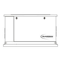
Guardian 5240 Installation And Owner's Manual (72 pages)
7, 10, 13 and 16kW Air-cooled, Automatic Standby Generators
Brand:
Guardian
| Category:
Portable Generator
| Size: 7.48 MB
Table of Contents
Introduction
2
Read this Manual Thoroughly
2
Contents
2
Operation and Maintenance
2
How to Obtain Service
2
Table of Contents
3
Safety Rules
4
Standards Index
5
Section 1 - General Information
6
Unpacking/Inspection
6
Protection Systems
6
NEC Requirement for Arc Fault Circuit Interruption Breaker for Bedrooms
6
The Generator
7
Specifications
8
System Set LED
9
Fuel Requirements and Recommendations
9
Fuel Consumption
9
Reconfiguring the Fuel System
10
Location
11
Battery Requirements
12
Battery Installation
12
The Battery
13
Section 2 - Post Installation Start-Up and Adjustments
14
Before Initial Startup
14
Check Transfer Switch Operation
14
Electrical Checks
15
Generator Tests under Load
15
Checking Automatic Operation
16
Adjusting the Fuel Regulator - 7Kw (Natural Gas Only)
16
Engine Governor Adjustment
17
Voltage Regulator Adjustment
17
Section 3 - Operation
18
Using the AUTO/OFF/MANUAL Switch
18
Automatic Transfer Operation
18
Sequence of Automatic Operation
19
Manual Transfer Operation
19
Setting the Exercise Timer
20
Protection Systems
20
Section 4 - Maintenance
22
Fuses
22
Checking the Engine Oil Level
22
Changing the Engine Oil
23
Changing the Engine Air Cleaner
23
Spark Plug(S)
24
Battery Maintenance
25
Adjusting
25
Valve Clearance
25
Cooling System
26
Attention after Submersion
26
Corrosion Protection
27
Out of Service Procedure
27
Service Schedule
28
Section 5 - Troubleshooting
29
Troubleshooting Guide
29
Section 6 - Notes
30
Section 7 - Electrical Data
31
Section 8 - Exploded Views and Parts Lists
42
Section 9 - Mounting Dimensions
68
Section 10 - Warranty
70
Advertisement
Related Products
Guardian 5241
Guardian 5280
Guardian 5281
Guardian 5242
Guardian 5282
Guardian 5283
Guardian 5284
Guardian 5243
Guardian 5244
Guardian 55 ES
Guardian Categories
Air Cleaner
Humidifier
Safety Equipment
Mobility Aid
Portable Generator
More Guardian Manuals
Login
Sign In
OR
Sign in with Facebook
Sign in with Google
Upload manual
Upload from disk
Upload from URL