Sign In
Upload
Manuals
Brands
GSK Manuals
Control Systems
GSK988TB
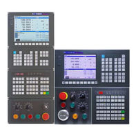
GSK GSK988TB CNC Turning Center Manuals
Manuals and User Guides for GSK GSK988TB CNC Turning Center. We have
1
GSK GSK988TB CNC Turning Center manual available for free PDF download: Manual
GSK GSK988TB Manual (531 pages)
Brand:
GSK
| Category:
Control Systems
| Size: 7 MB
Table of Contents
Table of Contents
7
Chapter 1 Programming Fundamental
21
Program Edit
23
CNC System of Machine Tools and CNC Machine Tools
24
Programming Fundamentals
25
Increment System
26
Max. Travel
27
Reference Point
28
Interpolation Function
29
Coordinate Value and Dimension
30
Diameter Programming and Radius Programming
31
Decimal Programming
32
Conversion between the Metric and the Inch
33
Program Name
35
Word
36
Block Number
45
Execution Sequence of Word
46
Chapter 2 G Codes
47
Omitting Word Input
50
Relevant Definitions
51
Linear Interpolation G01
52
Circular Interpolation G02, G03
53
Spiral Interpolation G02, G03
56
Dwell G04
58
Cylindrical Interpolation 7.1
59
Programmable Parameter Input G10
63
Setting a Workpiece Coordinate System's Offset Amount
64
Additional Workpiece Coordinate System Setting
65
Setting a Tool Offset Value
66
Polar Coordinate Interpolation G12.1, G13.1
67
Metric/Inch Switch G20, G21
69
Stored Travel Check G22, G23
70
Skip Interpolation G31
71
Automatic Tool Offset G36, G37
73
Reference Point Function
75
Nd, 3Rd, 4Th Reference Point Return
76
Selecting Machine Coordinate System Position G53
77
Workpiece Coordinate System Setting G50
78
Workpiece Coordinate System Selection G54~G59
79
Additional Workpiece Coordinate System G54.1
81
Local Coordinate System Setting G52
82
Plane Selection Code G17~G19
84
Fixed Cycle Code
85
Radial Cutting Cycle G94
88
Multiple Cycle Codes
91
Monontone Change Is Not Observed Along the Z Axis
97
Radial Roughing Cycle G72
98
Closed Cutting Cycle G73
102
Finishing Cycle G70
108
Radial Grooving Multiple Cycle G75
112
Notes for Multi Cycle Machining
116
Thread Cutting with Constant Lead G32
117
Thread Cutting with Variable Lead G34
120
Thread Cutting Cycle G92
121
Multiple Thread Cutting Cycle G76
124
Feedrate Per Minute G98/G94, Feedrate Per Rev G99/G95
132
Drilling/Boring Fixed Cycle Code
133
End Drilling Cycle G83 /Side Drilling Cycle G87
134
End Boring Cycleg85 / Side Boring Cycle G89
139
Cancelling Drilling/Boring G80
140
Notes for Drilling/Boring Cycle
141
End Rigid Tapping Cycle (G84) / Side Rigid Tapping Cycle (G88)
142
End Common Tapping Cycle G84/Side Common Tapping Cycle G88
148
Automatic Chamfering Function
152
Function of Directly Inputting Graphic Dimension
154
Macro Code
158
System Variable
160
Operation and Jump Code
164
Macro Program Statement and NC Statement
169
Slant Axis Control
172
Code System B
174
Absolute Code and Incremental Code G90, G91
175
Chapter 3 MSTF Codes
177
Optional Stop M01
178
Subprogram Call M198
179
Return from Subprogram M99
180
Standard M Codes for Standard Ladder
181
Notes for M Codes
182
Spindle Override
183
Tool Function
186
Tool Life Management
190
Tool Life Count Restarting M Code
191
Automatically Inputting a Tool Life Data
192
Process When the Tool Life End
194
Chapter 4 Tool Nose Radius Compensation
197
Imaginary Tool Nose Direction
198
Compensation Value Setting
201
G40/G41/G42 Command Function
202
Compensation Direction
203
Notes
205
Application
206
Tool Nose Radius Compensation Offset Path
207
Tool Traversing in Offset Mode
209
Tool Traversing in Offset Canceling Mode
214
Tool Interference Check
215
Codes for Canceling Compensation Vector Temporarily
217
Particulars
221
Chapter 1 Overview
229
Setting the System
231
System Host Machine
232
Button Definition
233
Key Definition on Machine Operation Panel
236
Chapter 2 Power On/Off and Safety Protection
243
Overtravel Protection
244
Emergency Operation
246
Chapter 3 Display
247
Absolute Coordinate Display
248
Relative Coordinate Display
249
Machine Coordinate Display
250
Relative Coordinate Setting
251
Clearing the Machining Workpiece Number
252
MDI Program
254
Program Restart
255
Parameter Setting
256
Pitch Compensation
258
System Message
259
System File Management
262
The Ladder Diagram
263
PLC Data
266
PLC Status
268
GSK-Link Communication Setting
269
O Unit
276
Setting Page Set
277
Tool Offset Setting
278
Tool Life
279
CNC Setting
281
Coordinate Setting
282
Setting the System Time
283
System IP Setting
284
System Debugging Function
285
Macro Variable
287
Message Display Page Set
288
History Record
289
System Diagnosis
290
O Diagnosis
293
Figure Display Page Set
294
The Machined Graph Path Display
295
Simultaneous Graph Display
296
Chapter 4 Editing and Managing the Program
299
Opening a Program
300
Saving as
301
Deleting a Program
302
Arranging a Programs
303
Rewriting a Program
306
Block Notes
307
Generating a Block Number
308
Chapter 5 Manual Operation
309
Manual Feeding
310
Incremental Feeding
312
MPG Feeding
313
MPG Retreating
314
MPG Retreat Operation Method
315
Rules for each Code's Reverse Movement
316
Chapter 6 Auto Operation
317
Program Running
318
Running from the Arbitrary Block
319
Automatic Running Stop
320
Manual Data Input (MDI) Running
321
Running from Arbitrary Block
322
Automatic Running Status Control
325
S.T Lock
326
Single Block Running
327
Rapid Movement Override
328
Steps of Program Restart
329
S.T Function Treatment of Program Restart
331
Function Limitation
332
Cautions
334
Chapter 7 Tool Offset & Tool Setting
337
Measuring Input Mode
338
Input Mode
339
Clearing the Tool Offset Value or the Wearing Value
341
Tool Setting in the Fixed Position
342
Trial Tool Cutting (the Machine Zero Return Tool Setting)
343
Position Record
345
Automatic Tool Compensation
346
Chapter 8 Graph Setting & Display
349
Path Graph Display and Operation
350
Simultaneous Graph Display and Operation
351
Chapter 9 Usage of USB Flash Disk
353
Data Backup
354
Backup of Servo Parameter
355
Leading-In of Servo Parameter
357
Chapter 10 Machine Example
359
Combined Machining
363
Appendix
370
Appendix 1 Parameters
372
Appendix 1.1 Parameter for "Setting
373
Appendix 1.3 Parameters of Axis Control/Setting Unit
374
Appendix 1.4 Parameter of the Coordinate System
379
Appendix 1.5 Parameter of the Stroke Detection
383
Appendix 1.6 Parameter of the Feedrate
387
Appendix 1.7 Parameter of Control of Acceleration and Deceleration
393
Appendix 1.8 Parameter of Servo and Backlash Compensation
396
Appendix 1.9 Parameter of Input/Output
398
Appendix 1.10 Parameter of Display and Editing
405
Appendix 1.11 Parameter of Programming
409
Appendix 1.12 Parameter of Screw Pitch Error Compensation
413
Appendix 1.13 Parameter of the Spindle Control
416
Appendix 1.14 Parameter of Tool Compensation
426
Appendix 1.15 Parameter of Canned Cycle
432
Appendix 1.15.2 Parameter of Thread Cutting Cycle
434
Appendix 1.16 Parameter of Rigid Tapping
436
Appendix 1.17 Parameter of Polar Coordinate Interpolation
440
Appendix 1.18 Parameter of User Macro Program
441
Appendix 1.19 Parameter of the Skip Function
445
Appendix 1.20 MPG Retraction Parameter
447
Appendix 1.21 Parameter of Graphic Display
448
Appendix 1.23 Parameter for Tool Life Span Administration
449
Appendix 1.24 Parameter of MPG Feed
453
Appendix 1.25 Parameters of Program Restart
455
Appendix 1.26 Polygon Machining Parameter
456
Appendix 1.27 Parameter of PLC Axis Control
457
Appendix 1.28 Parameter of the Basic Function
461
Appendix 1.29 Parameter for Slopping Axis Control
463
Appendix 1.30 Parameter of Gsklink Communication Function
464
Appendix 2 Standard PLC Function Configuration
466
Appendix 2.1.3 GSK988TA-H Standard Panel on Machine Tool
467
Appendix 2.1.4 GSK988TB Standard Panel on the Machine Tool
468
Appendix 2.2.1 High Speed I/O Interface
469
Appendix 2.2.3 Interface of the Handhold Box
472
Appendix 3 Interface Explanation
474
Appendix 3.1.2 Encoder Interface CN21 and CN22
475
Appendix 3.2 Rear Cover Interface of Machine Tool Operation Panel
476
Appendix 3.2.1 Dedicated Wave Band Switch Interface
477
Appendix 3.2.4 Communication Interface CN57
478
Appendix 4 Alarm Troubleshooting
480
Appendix 5 Installation Layout
516
Appendix 5.1.1 GSK988TA1 and Its Accessory
517
Appendix 5.1.1.2 Outline Installation Dimension of GSK988TA1 Operation Panel MPU-08E
518
Appendix 5.1.2 GSK988TA1-H & Accessory
519
Appendix 5.1.3 GSK988TA and Its Accessory
520
Appendix 5.1.3.2 Appearance Installation Dimension of GSK988TA Operation Panel MPU-08
521
Appendix 5.1.4 GSK988TA-H & Accessory
522
Appendix 5.1.5 GSK988TB and Its Accessory
523
Appendix 5.1.5.2 GSK988TB-H Host Outline Installation Dimension
524
Appendix 5.1.6 I/O Unit Appearance Dimension
525
Appendix 5.1.6.3 IOL-02F Appearance Dimension
526
Appendix 6 List of Normal Operation
528
Advertisement
Advertisement
Related Products
GSK GSK983Ma
GSK GSK980TDc
GSK GSK988TA
GSK GSK988TA1
GSK GSK983Ta-H
GSK GSK983Ta-V
GSK GSK983M-H
GSK GSK983M-V
GSK GSK928TE
GSK GSK928TC
GSK Categories
Control Systems
Medical Equipment
Servo Drives
Controller
Engine
More GSK Manuals
Login
Sign In
OR
Sign in with Facebook
Sign in with Google
Upload manual
Upload from disk
Upload from URL