Sign In
Upload
Manuals
Brands
GREE Manuals
Air Conditioner
GRS-CQ14Pd/NaEK
GREE GRS-CQ14Pd/NaEK Manuals
Manuals and User Guides for GREE GRS-CQ14Pd/NaEK. We have
1
GREE GRS-CQ14Pd/NaEK manual available for free PDF download: Service Manual
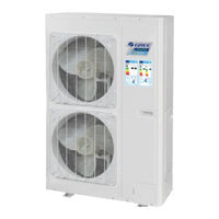
GREE GRS-CQ14Pd/NaEK Service Manual (130 pages)
Air-to-water Heat Pump Split Versati series
Brand:
GREE
| Category:
Air Conditioner
| Size: 9.76 MB
Table of Contents
Table of Contents
2
Product
6
Product Data
6
Lineup
6
Main Unit
6
Water Tank
7
Nomenclature
7
Main Unit
7
Product Features
8
General
8
Features
8
Operating Principle
9
Schematic Diagram
9
Technical Data
10
Parameter List
10
Nominal Working Conditions
14
Operation Range
14
Electric Data
14
Capacity Correction
15
Outline Dimensions
16
Outline Dimensions of Outdoor Unit
16
Outline Dimensions of Indoor Unit
18
Explosive Views and Part Lists
19
Supply Scope
29
Design and Selection
31
Installation Example
31
Model Selection
33
Speculations of Power Supply
33
Operation Conditions
33
Flowchart of Model Selection
34
Design Principle
34
Selection of the Underfloor Coils
34
Calculation of Unit Load for Floor Heating
34
Selection of Tube Spacing of the Underfloor Coils
35
Selection of Loop Quantity of Coils for each Room
35
Type of Underfloor Coils
35
Selection of Loop Quantity for each Room
36
Quantity and Location of the Water Traps and Collectors
36
Design Requirements on Loop Quantity for Circulation Water
36
Requirements on Installation of the Water Trap (Collector)
38
Section of FCU
38
FCU Type Selection
38
Matching of Capacity
38
Selection of the Water Tank
39
Specifications of the Water Tank
39
Volume Selection of the Water Tank
39
Selection Based on Water Consumption Per Capita
39
Selection Based on Sanitary Utensils
40
Selection of the Water Tank
40
Examples for Model Selection
40
General Introduction to the Example Project
40
Heat Load Calculation
40
Load Calculation of a Single Floor
40
Arrangement Design of the Underfloor System for a Single Floor
41
Arrangement Design of the Underfloor System for the Bath Room
41
Arrangement Design of the Underfloor System for the Master and Bath Rooms
41
Check
41
Model Selection
42
Unit Control
43
Integral Control Concept
43
Control Principle Diagram
43
Control Flowchart
46
Main Control Logics
46
Cooling
46
Control to the Compressor
46
Freeze Protection
47
Heating
47
Control to the Compressor
47
Over-Temperature Protection
47
Control to the Auxiliary Electric Heater
47
Water Heating
47
Water Heating by the Main Unit
47
Water Heating by the Solar System
48
Shutdown
48
Control to the Compressor
48
Control to the Fan
48
Control to the 4-Way Valve
49
Control to the Water Pump
49
Control the Electrostatic Expansion Valve
49
Protection Control
49
Controller
50
External View
50
Keys & Indicating Leds
50
Standby Page and Homepage
51
Operation Instructions
52
On/Off
52
Function Setting
53
Parameter Setting (Parameter Set)
73
View
76
General Setting
81
Key Lock
82
Unit Installation
84
Installation Guides
84
Installation Positions of the Outdoor Unit
85
Installation Positions of the Indoor Unit
85
Matters Need Attention
85
Filed Supplied Pipes and Valves
85
Service Tools
87
Instalaltion Instructions
88
Installation Examples
88
Pre-Installation
89
Selection of Installation Location
89
Outline Dimension of Outdoor Unit
90
Installation Clearance Data
92
Outline Dimension of Indoor Unit
92
Installation Clearance Data
93
Installation of Water Tank
93
Electric Wiring
96
Wiring of the Terminal Board
99
Wiring of the 2-Way Valve
101
Wiring of The3-Way Valve
102
Wiring of Other Auxiliary Heat Sources
103
Wiring of the Gate-Controller
103
Wiring of the Remote Air Temperature Sensor
104
Wiring of the Thermostat
105
Wiring of the Control
107
Commissioning and Trial Run
109
Check before Startup
109
Test Run
110
Test Operation & Troubleshooting & Maintenance
112
Trial Run
112
Check for Wiring
112
Check for the Water System
112
Check for the Communication System
112
Trial Run
113
Error Code List
113
Flow Chart of Troubleshooting
115
Comp High-Pressure Protection E1
115
Comp Low- Pressure Protection E3
116
Comp Discharge Temp Protection E4
117
Overload Protection of Compressor or Driver Error
118
DC Fan Error EF
119
Temperature Sensor Error
119
Communication Malfunction E6
120
Capacity Switch Error (Code:"C5")
121
Diagnosis of Driving
121
Diagnosis Flowchart of Driving of Single-Phase Unit and Three-Phase Unit
121
Daily Maintenance and Repair
126
Daily Maintenance
126
Troubleshooting
127
Repair
127
Key Components
127
Charging and Discharging of Refrigerant
129
Advertisement
Advertisement
Related Products
GREE GRS-CQ14Pd/NaEM
Gree Versati III GRS-CQ14Pd/NhH-M
Gree Versati III GRS-CQ14Pd/NhH-E
Gree GRS-CQ14Pd/NhG3-E
Gree GRS-CQ14Pd/NhG3-M
Gree GRS-CQ14Pd/NhG4-E
Gree GRS-CQ14Pd/NhG4-M
Gree GRS-CQ12Pd/NhG3-E
Gree GRS-CQ16Pd/NhG3-E
GREE GRS-CQ12Pd/NaEK
GREE Categories
Air Conditioner
Heat Pump
Dehumidifier
Controller
Chiller
More GREE Manuals
Login
Sign In
OR
Sign in with Facebook
Sign in with Google
Upload manual
Upload from disk
Upload from URL