Sign In
Upload
Manuals
Brands
GEM Manuals
Control Unit
650TL
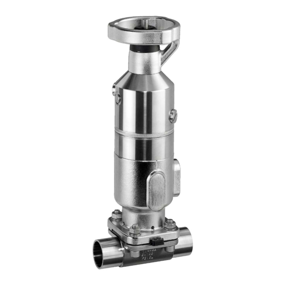
User Manuals: GEM 650TL Diaphragm valve
Manuals and User Guides for GEM 650TL Diaphragm valve. We have
2
GEM 650TL Diaphragm valve manuals available for free PDF download: Operating Instructions Manual
GEM 650TL Operating Instructions Manual (84 pages)
Manually operated diaphragm valve
Brand:
GEM
| Category:
Control Unit
| Size: 9 MB
Table of Contents
Table of Contents
3
Allgemeines ......................................................... 4 18 Inspektion und Wartung
4
Hinweise
4
Verwendete Symbole
4
Begriffsbestimmungen
4
Warnhinweise
4
Sicherheitshinweise
5
Produktbeschreibung
5
Aufbau
5
Beschreibung
5
Steuerfunktion ............................................... 6 20 Rücksendung
6
Funktion ......................................................... 6 19 Entsorgung
6
Optische Stellungsanzeige
6
Bestimmungsgemäße Verwendung
6
Bestelldaten
7
Bestellcodes
7
Bestellbeispiel
9
Technische Daten
10
Medium
10
Druck
10
Produktkonformitäten
11
Mechanische Daten
12
Abmessungen
12
Antriebsmaße
12
Körpermaße Durchgangskörper
15
Körpermaße Bodenablass- und T-Körper
25
Anwendungsfall
26
Herstellerangaben
26
Lieferung
26
Verpackung
26
Transport
26
Lagerung
26
Auslieferungszustand
26
Einbau in Rohrleitung
27
Einbauvorbereitungen
27
Einbaulage
27
Einbau mit Schweißstutzen
27
Einbau mit Clampanschluss
28
Einbau mit Gewindestutzen
28
Pneumatischer Anschluss
28
Steuerfunktion
28
Steuermedium Anschließen
29
Hub- und Schließbegrenzung
29
Schließbegrenzung Einstellen (GEMÜ 650 0TL, 0RL, 0LL)
29
Schließ- und Hubbegrenzung Einstellen (GEMÜ 650 1TL, 1RL, 1LL, 1HL, 1ML, 1SL / 650 2TL, 2RL, 2LL, 2HL, 2ML, 2SL)
30
14 Näherungsinitiatoren
31
Näherungsinitiatoren Einstellen
31
Bedämpfungsstück Einstellen
32
Inbetriebnahme
32
Betrieb
32
Steuerfunktion 1
32
Fehlerbehebung
33
Inspektion und Wartung
35
Ersatzteile
35
Ersatzteile 0TL
35
Ersatzteile 1TL; 2TL
35
Antrieb Demontieren
36
18.3 Membrane Demontieren
36
Schinenrichtlinie 2006/42/EG, Anhang II B
40
Richtlinie 2014/68/EU
41
Information .................................................... 43 18 Inspection and Maintenance
43
General Information ............................................. 43 17 Troubleshooting
43
Symbols Used
43
Definition of Terms
43
Warning Notes
43
Safety Information
44
Construction
44
Product Description
44
Control Function ............................................. 45 19 Disposal
45
Function
45
Optical Position Indicator
45
Gemü Conexo
45
Correct Use
45
Order Data
46
Order Codes
46
Order Example
48
Technical Data
49
Medium
49
Pressure
49
Product Conformity
50
Mechanical Data
51
Dimensions
51
Actuator Dimensions
51
Body Dimensions of 2/2-Way Body
54
Body Dimensions of Tank Bottom Valve Body and T Body
64
Application
65
Manufacturer's Information
65
Delivery
65
Packaging
65
Transport
65
Storage
65
Condition as Supplied to Customer
65
Installation in Piping
66
Preparing for Installation
66
Installation Position
66
Installation with Butt Weld Spigots
66
Installation with Clamp Connections
67
Installation with Threaded Spigots
67
Pneumatic Connection
67
Control Function
67
Connecting the Control Medium
68
Stroke Limiter and Seal Adjuster
68
Schließbegrenzung Einstellen (GEMÜ 650 0TL, 0RL, 0LL)
68
Schließ- und Hubbegrenzung Einstellen
69
(Gemü 650 1Tl, 1Rl, 1Ll, 1Hl, 1Ml, 1Sl / 650 2Tl, 2Rl, 2Ll, 2Hl, 2Ml, 2Sl)
69
Proximity Switches
70
Setting Proximity Switches
70
Setting the Damping Piece
71
Commissioning
71
Operation
71
Control Function 1
71
Troubleshooting
72
Inspection and Maintenance
74
Spare Parts 0TL
74
Spare Parts 1TL; 2TL
74
18.2 Removing the Actuator
75
18.3 Removing the Diaphragm
75
Mounting the Compressor
75
Mounting the Diaphragm
76
Mounting the Actuator
78
Returns
78
EC Machinery Directive 2006/42/EC, Annex II B
79
Manufacturer's Declaration
80
Sure Equipment Directive 2014/68/EU
80
Advertisement
GEM 650TL Operating Instructions Manual (42 pages)
Manually operated diaphragm valve
Brand:
GEM
| Category:
Control Unit
| Size: 7 MB
Table of Contents
Table of Contents
3
1 General Information
4
Information
4
Symbols Used
4
Definition of Terms
4
Warning Notes
4
2 Safety Information
5
Description ..................................................... 5 19 Disposal
5
Function ......................................................... 6 20 Returns
6
Control Function
6
3 Product Description
5
4 Gemü Conexo
6
5 Correct Use
7
6 Order Data
7
Order Codes
7
Order Example
9
7 Technical Data
10
Medium
10
Pressure
10
Product Conformity
11
Mechanical Data
12
8 Dimensions
12
Actuator Dimensions
12
Body Dimensions of 2/2-Way Body
15
Body Dimensions of Tank Bottom Valve Body and T Body
25
9 Application
26
10 Manufacturer's Information
26
Delivery
26
Packaging
26
Transport
26
Storage
26
Condition as Supplied to Customer
26
11 Installation in Piping
27
Preparing for Installation
27
Installation Position
27
Installation with Butt Weld Spigots
27
Installation with Clamp Connections
28
Installation with Threaded Spigots
28
12 Pneumatic Connection
28
Control Function
28
Connecting the Control Medium
29
13 Stroke Limiter and Seal Adjuster
29
Setting the Seal Adjuster (GEMÜ 650 0TL)
29
Setting the Closing and Opening Stroke Limiter (GEMÜ 650 1TL/650 2TL)
30
14 Proximity Switches
31
Setting Proximity Switches
31
Setting the Damping Piece
32
15 Commissioning
32
16 Operation
32
Control Function 1
32
17 Troubleshooting
33
18.1 Spare Parts
35
Spare Parts 0TL
35
Spare Parts 1TL; 2TL
35
18 Inspection and Maintenance
35
18.4 Mounting the Compressor
36
19 Disposal
40
EC Machinery Directive 2006/42/EC, Annex II B
40
20 Returns
40
21 EU Declaration of Incorporation According to the
40
22 Manufacturer's Declaration According to the Pres- 6 Sure Equipment Directive 2014/68/EU
41
Advertisement
Related Products
GEM 651
GEM 65150D60341314D1B011503
GEM 653
GEM 654
GEM 654-0TH
GEM 654-D
GEM 654-MAG
GEM 656
GEM 655
GEM 653-T
GEM Categories
Control Unit
TV Mount
Musical Instrument
Measuring Instruments
Valve Positioners
More GEM Manuals
Login
Sign In
OR
Sign in with Facebook
Sign in with Google
Upload manual
Upload from disk
Upload from URL