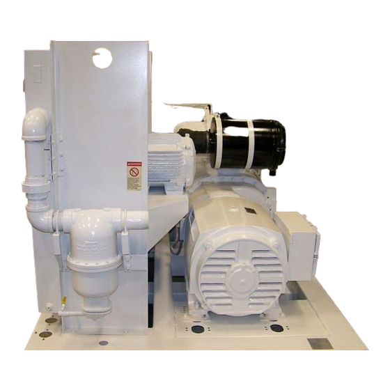
Sign In
Upload
Manuals
Brands
Gardner Denver Manuals
Air Compressor
EAQ99T
Gardner Denver EAQ99T Manuals
Manuals and User Guides for Gardner Denver EAQ99T. We have
1
Gardner Denver EAQ99T manual available for free PDF download: Operating And Service Manual
Gardner Denver EAQ99T Operating And Service Manual (78 pages)
Brand:
Gardner Denver
| Category:
Air Compressor
| Size: 1.85 MB
Table of Contents
Maintain Compressor Reliability and Performance with
2
Genuine Gardner Denver Compressor Parts and Support Services
2
Instructions for Ordering Repair Parts/Remanufactured Airends
2
Warning - Prohibition - Mandatory Label Information
3
Safety Precautions
5
Table of Contents
6
Index
7
List of Illustrations
9
Section 1, General Information
10
Figure 1-1 - Compression Cycle
10
Figure 1-2 - Starter Box
11
Figure 1-3 - Control Box
11
Figure 1-4 - Compressor / Motor Side
12
Figure 1-5 - Cooler / Reservoir Side
12
Figure 1-6 - Air/Oil Flow Diagram
13
Section 2, Installation
14
Figure 2-1 - Typical Compressor Room
15
Figure 2-2 - Air Flow Chart
15
Figure 2-3 - Cold Weather Installation
17
Figure 2-4 - Inlet Line Lengths
18
Figure 2-5 - Heat Exchanger (Oil Cooler) Approximate Water Flow
20
Figure 2-6 - Aftercooler Approximate Water Flow
20
Figure 2-7 - Series Piping
22
Figure 2-8 - Parallel Piping
22
Section 3, Starting & Operating Procedures
25
Section 4, Controls & Instrumentation
30
Figure 4-1 - Key Pad
31
Figure 4-2 - Schematic Tubing Diagram
32
Figure 4-3 - Blowdown Valve
33
Figure 4-4 - Minmum Discharge Pressure/Check Valve
33
Figure 4-5 - Inlet Valve
34
Figure 4-6 - Shuttle Valve
35
Figure 4-7 - Turn Valve - Electra-Saver Only
36
Figure 4-8 - Control Schematic - Compressor Unloaded - Constant Speed Mode
39
Figure 4-9 - Control Schematic - Compressor at Full Load - Constant Speed Mode
40
Figure 4-10 - Control Schematic - Compressor Unloaded - Low Demand Mode or Auto Mode
41
Figure 4-11 - Control Schematic - Compressor at Full Load
42
Figure 4-12 - Control Schematic - Compressor Fully Unloaded - Low Demand Mode Switch off
43
Figure 4-13- Control Schematic - Compressor Fully Loaded - Low Demand Mode Switch on
44
Figure 4-14 - Wiring Diagram - Wye Delta
45
Figure 4-15 - Wiring Diagram - Less Starter
47
Section 5, Lubrication, Oil Cooler, Oil Filter & Separator
49
Figure 5-1 - Dew Point Chart °F
51
Figure 5-2 - Dew Point Chart °C
51
Figure 5-3 - Flow Diagram - Air/Oil System
52
Figure 5-4 - Oil Flow Diagram - Remote Overhead Mounted Cooler
53
Figure 5-5 - Cooler Drain Detail
54
Figure 5-6 - Oil Level Gauge
57
Figure 5-7 - Oil Change Interval
58
Figure 5-8 - Approximate Oil System Capacities
59
Figure 5-9 - Thermostatic Mixing Valve Element
61
Figure 5-10 - Water Control Valve
62
Figure 5-11 - Oil Separator
64
Section 6, Air Filter
67
Figure 6-1 - Heavy Duty Air Filter
67
Section 7, Coupling
69
Figure 7-1 - Installation of Coupling Cushions
69
Section 8, Maintenance Schedule
72
Section 9, Troubleshooting
74
Advertisement
Advertisement
Related Products
Gardner Denver EAQ99W
Gardner Denver ELECTRA-SAVER EAQ99Q
Gardner Denver ELECTRA-SAVER EAQ99R
Gardner Denver EAQ99S
Gardner Denver EAP99K
Gardner Denver ELECTRA-SAVER EAU99Q
Gardner Denver EAU99U
Gardner Denver EAP99L
Gardner Denver AUTO SENTRY EAU99P
Gardner Denver AUTO SENTRY EAU99M
Gardner Denver Categories
Air Compressor
Water Pump
Dehumidifier
Controller
Blower
More Gardner Denver Manuals
Login
Sign In
OR
Sign in with Facebook
Sign in with Google
Upload manual
Upload from disk
Upload from URL