Sign In
Upload
Manuals
Brands
Freedom Manuals
Measuring Instruments
R8100 SERIES
Freedom R8100 SERIES Manuals
Manuals and User Guides for Freedom R8100 SERIES. We have
2
Freedom R8100 SERIES manuals available for free PDF download: Operator's Manual, Testing
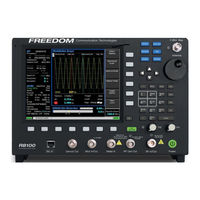
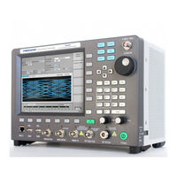
Freedom R8100 SERIES Operator's Manual (255 pages)
COMMUNICATIONS SYSTEM ANALYZER
Brand:
Freedom
| Category:
Measuring Instruments
| Size: 7 MB
Table of Contents
Table of Contents
2
Limited Warranty
11
Software License Agreement
12
1 Pre-Operation Overview
13
Scope of Manual
13
Safety Summary
13
Analyzer Grounding
13
Unit Is Live When Plugged in
13
Keep Away from Live Circuits
13
Explosive Atmosphere
13
Warnings and Cautions
14
Analyzer Operating Voltage
14
DC Power Source
14
Maximum Meter in Voltages
15
Replacement Fuses
15
Other Cautions
15
User Maintenance of Exterior Surfaces
15
Service
16
Replacement Parts Orders
16
Installation
16
Packing
16
Initial Set-Up
16
Warm-Up
16
Description
16
Figure 2.1-1 Front Panel Controls, Indicators, and Connectors
18
Figure 2.1-2 Left and Right Sides of the R8100 Needs New Photo
19
Technical Specifications
20
Operator Interface and Controls
21
Front Panel Control Keys
22
Front Panel Control Knobs
25
Front Panel Display and Indicators
26
2 Operation
30
Overview
30
Basic Navigation and Operator Control
30
Figure 3.1.1-1 Main Screen in Monitor Mode Showing Related Information in Grouped Display Zones
31
Figure 3.1.1-2 Main Display Area after Audio Zone Soft Key Press
32
Hot Keys for Fast Navigation in Monitor, Audio, Display and Meter Zones
33
Figure 3.1.1-4 Audio Zone Data Entry for Fixed 1 Khz Level
33
Operating Instructions
34
RF Zone / Monitor Mode
34
Figure 3.1.2-1 Outline Around Numeric Keypad Hot Keys
34
Figure 3.2.1-1 RF Zone Display Area Showing Monitor Mode Data
35
Figure 3.2.1-2 Monitor Mode Submenu after RF Zone Soft Key Press
36
Figure 3.2.1-3 Data Entry Window before and after Monitor Frequency Change
38
Figure 3.2.1-4 RF Zone Display Area after Monitor Frequency Change
38
RF Zone / Generate Mode
39
Figure 3.2.2-1 RF Zone Display Area Showing Generator Mode Data
39
Figure 3.2.2-2 Generator Mode Submenu after RF Zone Soft Key Press
40
RF Zone / Duplex Mode
41
Figure 3.2.3-1 RF Zone Display after Duplex Key Press
42
Figure 3.2.4-1 Audio Zone Display with the R8100 in Generate Mode
44
Figure 3.2.4-2 Audio Zone Display with the R8100 in Monitor Mode
44
Figure 3.2.4.1-1 Audio Zone Submenu in Monitor Mode
45
Figure 3.2.4.2-1 Format Submenu in Audio Zone
46
Figure 3.2.4.2-2 DTMF Table Providing Additional Code Sequence Control
48
Figure 3.2.4.3-1 PL Table Showing Highlighted Entry Code
50
Figure 3.2.4.3-2 A/B Sequence Table Showing Highlighted Sequence
51
Figure 3.2.4.3-3 A/B Sequence Table Submenu for User Programmable Entries
52
Figure 3.2.4.3-4 5/6 Tone Entry Submenu
53
Figure 3.2.4.3-5 POCSAG Table Submenu
54
Figure 3.2.4.3-6 General Sequence Table Submenu
56
Figure 3.2.4.4-1 Audio Zone Submenu in Generator Mode
59
Display Zone
60
Figure 3.2.5-1 Display Zone Submenu after Select Display Soft Key Press
61
Figure 3.2.5.1-1 Trace Math Display
63
Figure 3.2.5.1-2 Demod at Marker Submenu
65
Figure 3.2.5.2-1 Display Zone Submenu for the Mod Scope
66
Figure 3.2.5.3-1 Display Zone Submenu for the Oscilloscope
68
Figure 3.2.5.4-1 Bar Graphs Screen in Display Zone
71
Meter Zone
73
Figure 3.2.5.5-1 General Seq Screen in Display Zone
73
Figure 3.2.6-1 Meter Zone Submenu Showing RF Scan Meter
74
Figure 3.2.6-2 Meter Zone Submenu after Select Meter Soft Key Press
74
Figure 3.2.6.1-1 RF Power Meter Screen
75
Figure 3.2.6.2-1 AC Volts Display
75
Figure 3.2.6.2-2 DC Volts Display
75
Figure 3.2.6.3-1 SINAD Display
76
Figure 3.2.6.3-2 Internal Distortion Display
76
Figure 3.2.6.4-1 Pl/Period Counter Screen
77
Figure 3.2.6.4-2 DPL Decode Screen
77
Figure 3.2.6.4-3 DTMF Decode Screen
77
Figure 3.2.6.4-4 2-Tone Decode Screen
78
Figure 3.2.6.4-5 5/6-Tone Decode Screen
78
Figure 3.2.6.4-6 General Sequence Decode Screen
79
Figure 3.2.6.5-1 Frequency Counter Screen
80
Instrument Menu
81
Figure 3.2.6.6-1 RF Scan Display
81
Figure 3.2.7-1 Submenu after Pressing Instrument Navigation Key
82
Figure 3.2.7.1-1 Submenu in Spectrum Analyzer Instrument Mode
83
Figure 3.2.7.2-1 Dual Display Mode
84
Figure 3.2.7.3-1 Tracking Generator Mode
85
Figure 3.2.7.3-2 Normalized Spectrum Analyzer Trace
88
Figure 3.2.7.4-1 Cable Fault Locator Mode
89
Test Menu
92
Figure 3.2.7.4-2 Frequency and Attenuation Entries in the Add Cable Type Submenu
92
Figure 3.2.8-1 Submenu after Pressing Test Navigation Key
93
Figure 3.2.8.1-1 Submenu after Pressing Presets Soft Key
94
Figure 3.2.8.1-2 Data Entry Mode after Pressing Save Configuration Soft Key
95
Figure 3.2.8.2-1 Test Mode Submenu
96
DMR Test Mode with MOTOTRBO
96
DMR Transmitter Tests
97
Figure 3.2.8.3-1
97
Figure 3.2.8.3.1-1 Submenu after Pressing DMR Soft Key in Generator Mode
98
Figure 3.2.8.3.1.2-1 Voice Loopback Recording
100
Figure 3.2.8.3.1.3-1 Power Profile Slot
102
Figure 3.2.8.3.1.3-2 Power Profile Frame with Markers
104
Figure 3.2.8.3.1.4-1 Submenu after Pressing DMR Soft Key in Monitor Mode
105
Figure 3.2.8.3.2-1 Submenu after Pressing DMR Soft Key in Generate Mode
106
Figure 3.2.8.3.2-2 Voice Loopback Playing
107
Figure 3.2.8.4.1-1 Main Screen in Monitor Mode Voice Frame Decode
110
Figure 3.2.8.4.1-2 Main Screen in Monitor Mode after Pressing the PROJECT 25 Soft Key
111
Figure 3.2.8.4.1.2-1 Test Pattern Submenu in P25 Monitor Mode
112
Figure 3.2.8.4.1.2-2 P25 Voice Recording
114
Figure 3.2.8.4.1.2-3 P25 Voice Loopback
115
Figure 3.2.8.4.1.3-1 P25 Eye Diagram Selection in Display Zone
116
Figure 3.2.8.4.1.3-2 Eye Diagram with Mon Mod Type WCQPSK and Display Mode Fade Away
117
Figure 3.2.8.4.1.3-3 P25 Voice Frame Decode
118
Figure 3.2.8.4.1.3-4 P25 Voice Frame Decode Unit to Unit
120
Figure 3.2.8.4.1.3-5 Constellation Plot (Symbols)
121
Figure 3.2.8.4.1.3-6 Ideal Constellation
122
Figure 3.2.8.4.1.3-7 Constellation Plot (Samples / Trajectories)
123
Figure 3.2.8.4.1.3-8 Distribution Plot of 1011 Hz Tone
124
Figure 3.2.8.4.2-1 Main Screen in Generate Mode after Pressing the PROJECT 25 Soft Key
125
Figure 3.2.8.4.2-2 P25 Generate Mode Test Patterns
125
Figure 3.2.8.4.2-3 P25 Voice Frame Encoder Submenu
127
Figure 3.2.8.5-1 Main Screen after Selecting P25 Trunk Test Mode
134
Figure 3.2.8.5-2 Main Screen after Pressing P25 Trunk Soft Key
135
Figure 3.2.8.5-4 P25 Trunk Band Plan Submenu
137
Figure 3.2.8.5-3 P25 Trunk Submenu after Starting BER Test after Registration
140
Figure 3.2.8.6-1 Main Screen in Monitor Mode after Selecting NXDN™ Test Mode
142
Figure 3.2.8.6.1-1 NXDN™ Monitor Mode
145
Figure 3.2.8.6.1-2 NXDN™ Voice Recording
146
Figure 3.2.8.6.1-3 NXDN™ Eye Diagram in Display Zone
147
Figure 3.2.8.6.1-4 NXDN™ Eye Diagram with Display in Fade Away Mode
148
Figure 3.2.8.6.2-1 NXDN™ Generate Mode
149
Figure 3.2.8.6.3-1 Main Screen after Selecting NXDN Trunk Test Mode
152
Figure 3.2.8.6.3-2 Main Screen after Pressing NXDN™ Trunk Soft Key
153
Figure 3.2.8.6.3-3 NXDN™ Trunk Submenu after Starting BER Test
154
Figure 3.2.8.6.1.4-1 NXDN Eye Diagram in Display Zone
157
Figure 3.2.8.8-1. Main Screen in Monitor Mode after Selecting TETRA Test Mode
158
Figure 3.2.8.8-2. Submenu after Pressing TETRA Soft Key in Monitor Mode
159
Figure 3.2.8.8-3. Error Vector Diagram
161
Figure 3.2.8.8-4. Power Profile Slot
162
Figure 3.2.8.8-5. Power Profile Frame with Markers
164
Figure 3.2.8.8-6. Mod Spec / Constellation (Symbols)
165
Figure 3.2.8.8-7. Ideal Constellation
166
Figure 3.2.8.8-8. Constellation (Samples / Trajectories)
166
Figure 3.2.8.8-9. Submenu after Pressing TETRA Soft Key in Generate Mode
167
Figure 3.2.8.9-2 Dpmr Monitor Mode
171
Figure 3.2.8.9-3 Dpmr Voice Recording
173
Figure 3.2.8.9-4 Dpmr Eye Diagram in Display Zone
174
Figure 3.2.8.9-5 Dpmr Eye Diagram with Display in Fade Away Mode
175
Figure 3.2.8.9-6 Dpmr Generate Mode
176
Figure 3.2.8.10.1-1 Main Screen in Monitor Mode after Selecting the P25 II Test Mode
179
Figure 3.2.8.10.1-2 Main Screen in Monitor Mode after Pressing the P25 II Soft Key
180
Figure 3.2.8.10.1.2-1 Test Pattern Submenu in P25 II Monitor Mode
181
Figure 3.2.8.10.1.3-1 HDQPSK Eye Diagram Selection in Display Zone
183
Figure 3.2.8.10.1.3-2 Eye Diagram of HCPM and Display Mode Fade Away
184
Figure 3.2.8.10.1.3-3 Distribution Plot of HDQPSK 1031 Hz Tone
185
Figure 3.2.8.10.1.3-4 Distribution Plot of HCPM 1031 Hz Tone
185
Figure 3.2.8.10.1.3-5 Power Profile Frame
186
Figure 3.2.8.10.1.3-6 Power Profile Slot with Markers
188
Figure 3.2.8.10.1.4-1 HDQPSK Frequency Constellation
188
Figure 3.2.8.10.1.4-2 HCPM Frequency Constellation
189
Figure 3.2.8.10.1.4-3 P25 Phase 2 Symbol Rate Measurement
190
Figure 3.2.8.10.2-1 Main Screen in Generate Mode after Selecting the P25 II Soft Key
191
Figure 3.2.8.10.2-2 P25 II Generate Mode Test Patterns
191
Figure 3.2.8.11-1. Autotune Submenu
194
Figure 3.2.8.11-2. Autotune Radio Test Setup
195
Figure 3.2.8.11-3 Autotune Activity Display
196
Figure 3.2.8.11-4. Autotune Test in Progress
197
Figure 3.2.8.11-5. Autotune Test Limits Submenu
199
Figure 3.2.8.11-6. Autotune Test Results Submenu
200
Figure 3.2.8.11-7. Autotune Test Preferences Submenu
201
Figure 3.2.8.12-1. Autoscript Submenu with no Scripts or Procedures Imported
204
Figure 3.2.8.12-2. View, Results Submenu with Results from a Procedure Execution Displayed
205
Figure 3.2.8.12-3. Use Toggle Selection to Enable or Disable Script Execution
206
Figure 3.2.8.12-4. Use Toggle Selection to Enable or Disable Script Execution
208
Figure 3.2.8.12-5. Example Script Showing Commands for Finding a Local FM Radio Station
209
Figure 3.2.8.12-6. Example Procedure Containing Several Scripts
210
Figure 3.2.9-1 Submenu after Pressing Settings Navigation Button on R8100 Front Panel
211
Settings Menu
211
Figure 3.2.9.2-1 Submenu after Pressing System Settings Soft Key in the Settings Menu
213
Figure 3.2.9.2-2 Pre-Amplifier Alert When Broadband Measurements Are Active
215
Figure 3.2.9.3-1 Submenu after Pressing Network Setup Soft Key in the Settings Menu
218
Figure 3.2.9.4-1 Submenu after Pressing Messages Soft Key in the Settings Menu
220
Figure 3.2.9.5-1 Submenu after Pressing about Soft Key in the Settings Menu
221
Figure 3.2.9.5-2 Settings/About/Protocols Screen
221
Figure 3.2.9.5-3 Settings/About/Versions Screen
222
Figure 3.2.9.5.1-1 Alert Screen as R8100 Finds a Valid Update on a USB Flash Drive
223
Figure 3.2.9.6-1 Submenu after Pressing Options Soft Key in the Settings Menu
224
Figure 3.2.10-1 File Folder Location and Names for R8100 Screen Captures
225
Screen Capture
225
3 Remote Operation
226
BIOS Power-Loss Setup
226
Figure 4-1 Remote Front Panel
226
DHCP Server Setup
227
Network Port Setup
228
Figure 4.3-1 Network Connection Security Alert
228
Computer Setup
229
Setup
229
Control
230
Disable Remote Access
230
Verification / Troubleshooting Information
230
4 Test Applications
232
FM Transmitter Testing
232
Basic FM Transmitter Testing - Initial Setup
232
Figure 5.1.1-1 Setup for FM Transmitter Testing
232
Transmit Power, Frequency, and Frequency Deviation Measurements
233
Modulation Measurements
233
Off-The-Air Measurements
234
FM Receiver Testing
234
Basic FM Receiver Testing - Initial Setup
234
Receiver Distortion Measurement
235
Figure 5.2.1-1 Setup for FM Receiver Testing
235
SINAD Measurement
236
Modulation Acceptance Bandwidth
236
Figure 5.3-1 Connections for Cable Fault Testing
237
Figure 5.3.1-1 Cable Fault Instrument Display
239
Appendix A – Glossary (List of Abbreviations and Acronyms)
246
Appendix B – Tone and Code Specifications
249
Table B-3 Private-Line (PL) Codes
250
Table B-4 5/6 Tone Paging Tones
251
Table B-7 POCSAG Numeric Character Set
252
Appendix C – R8100 Field Calibration Procedure
254
Revision History
255
Advertisement
Freedom R8100 SERIES Testing (4 pages)
Testing Motorola P25 Phase 2 Radios
Brand:
Freedom
| Category:
Measuring Instruments
| Size: 0 MB
Table of Contents
Scope
2
Motorola CPS and Tuner Software
2
Radio Configuration
2
Conducting P25 Phase 2 Tests with the R8000
2
Transmitter Tests
2
Modulation Fidelity
3
Radio Setup
3
R8000 Setup
3
Begin Test
3
Receiver Test
4
Digital Sensitivity (BER)
4
Advertisement
Related Products
Freedom R8000 Series
Freedom RASM Series
Freedom RWM Series
Freedom RWD Series
Freedom RWH Series
Freedom Harris XL-200
Freedom Categories
Indoor Furnishing
Measuring Instruments
Camera Accessories
Battery Charger
Boat
More Freedom Manuals
Login
Sign In
OR
Sign in with Facebook
Sign in with Google
Upload manual
Upload from disk
Upload from URL