Sign In
Upload
Manuals
Brands
Freedom Manuals
Measuring Instruments
R8000 Series
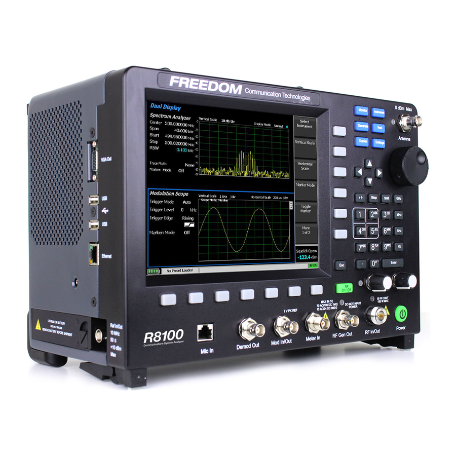
Freedom R8000 Series System Analyzer Manuals
Manuals and User Guides for Freedom R8000 Series System Analyzer. We have
4
Freedom R8000 Series System Analyzer manuals available for free PDF download: User Manual, Testing
Freedom R8000 Series User Manual (72 pages)
Communications Systems Analyzer
Brand:
Freedom
| Category:
Measuring Instruments
| Size: 1 MB
Table of Contents
Table of Contents
4
Introduction
9
Scope
9
Supported Models
9
Required Options
9
Motorola APX Portable Radio Test Setup
10
Cable Sweep
10
Test Hardware
11
APX Test Setup
11
Table 3-1. Portable Test Hardware Table
11
Figure 3-1. APX Portable Test Setup Diagram
12
Motorola APX Portable Alignment and Test Descriptions
13
Tx PA Bias (Auto)
13
Table 4-1. Analyzer Configuration for Tx PA Bias (Auto) Alignment
13
Table 4-2. Tx PA Bias (Auto) Alignment Results
13
Reference Frequency
14
Table 4-3. Analyzer Configuration for Reference Frequency
14
Table 4-4. Reference Frequency Alignment Results
14
Table 4-5. Reference Frequency Test Results
14
TX Power out
15
Table 4-6. Analyzer Configuration for TX Power out
15
Table 4-7. Power Characterization Points Alignment Results
15
Table 4-8. Tx Power Characterization Alignment Results
16
TX Attenuator Limit
17
Table 4-9. Analyzer Configuration for Tx Attenuator Limit
17
Table 4-10. Tx Attenuator Limit Alignment Results
17
TX PA Saturation Reference
18
Table 4-11. Analyzer Configuration for Tx PA Saturation Reference
18
Table 4-12. Tx PA Saturation Reference Alignment Results
18
Tx Deviation Balance
19
Table 4-13. Analyzer Configuration for Tx Deviation Balance Alignment
19
Table 4-14. Tx Deviation Balance Alignment Results
19
Rx Front End Filter
20
Table 4-15. Analyzer Configuration for Rx Front End Filter Alignment
20
Table 4-16. Rx Front End Filter Alignment Results
20
Front End Gain
21
Table 4-17. Analyzer Configuration for Front End Gain Alignment
21
Table 4-18. Front End Gain Alignment Results
21
Rx VLIF DCA Phase Error
22
Table 4-19. Analyzer Configuration for Rx VLIF DCA Phase Error Alignment
22
Table 4-20. Rx VLIF DCA Phase Error Alignment Results
22
Rx Duty Cycle Adjustment
23
Table 4-21. Analyzer Configuration for Rx Duty Cycle Adjustment Alignment
23
Table 4-22. R Duty Cycle Adjustment Results
23
RF Power
24
Table 4-23. RF Power Test Results
24
Rx Distortion
25
Table 4-24. Analyzer Configuration for Rx Distortion Test
25
Table 4-25. Rx Distortion Test Results
25
Rx Analog Sensitivity (SINAD)
26
Table 4-26. Analyzer Configuration for Rx Analog Sensitivity (SINAD) Test
26
Table 4-27. Rx Analog Sensitivity (SINAD) Test Results
26
Noise Squelch Threshold
27
Table 4-28. Analyzer Configuration for Noise Squelch Threshold Test
27
Table 4-29. Noise Squelch Threshold Test Results
27
Modulation Fidelity
28
Table 4-30. Analyzer Configuration for Modulation Fidelity Test
28
Table 4-31. Modulation Fidelity Test Results
28
Symbol Deviation
29
Table 4-32. Analyzer Configuration for Symbol Deviation Test
29
Table 4-33. Symbol Deviation Test Results
29
P25 Phase II Modulation Fidelity
30
Table 4-34. Analyzer Configuration for P25 Phase 2 Modulation Fidelity Test
30
Table 4-35. P25 Phase 2 Modulation Fidelity Test Results
30
P25 Phase II Symbol Deviation
31
Table 4-36. Analyzer Configuration for P25 Phase 2 Symbol Deviation Test
31
Table 4-37. P25 Phase 2 Symbol Deviation Test Results
31
Rx Digital Sensitivity (P25 BER)
32
Table 4-38. Analyzer Configuration for Rx Digital Sensitivity (P25 BER) Test
32
Table 4-39. Rx Digital Sensitivity (P25 BER) Test Results
32
Rx Sensitivity (P25 Phase II BER)
33
Table 4-40. Analyzer Configuration for Rx Sensitivity (P25 Phase II BER) Test
33
Table 4-41. Rx Sensitivity (P25 Phase II BER) Test Results
33
Voice Modulation (Internal)
34
Figure 4-1. Place Keyed Radio Next to Analyzer Speaker
34
Table 4-42. Analyzer Configuration for Voice Modulation (Internal) Test
34
Figure 4-2. Adjust Analyzer Volume until about 60% Rated System Deviation Is
35
Table 4-43. Voice Modulation (Internal) Test Results
35
Voice Modulation (External)
36
Table 4-44. Analyzer Configuration for Voice Modulation (External) Test
36
Table 4-45. Voice Modulation (External) Test Results
36
Motorola APX Mobile Radio Test Setup
37
Cable Sweep
37
Test Hardware
38
Motorola APX Mobile Test Setup
38
Table 5-1. Mobile Test Hardware Table
38
Motorola APX Mobile High Power Test Setup
39
Figure 5-1. Motorola APX Mobile Test Setup Diagram
39
Figure 5-2. Motorola APX Mobile High Power Test Setup Diagram
40
Motorola APX Mobile Alignment and Test Descriptions
41
Figure 6-1. Autotune Prompt When Test/Alignment Requires Switching Bands
41
Tx PA Bias
42
Table 6-1. Analyzer Configuration for Tx PA Bias Alignment
42
Table 6-2. Tx PA Bias Alignment Results
42
Reference Frequency
43
Table 6-3. Analyzer Configuration for Reference Frequency
43
Table 6-4. Reference Frequency Alignment Results
43
Table 6-5. Reference Frequency Test Results
44
TX Power out
45
Table 6-6. Analyzer Configuration for TX Power out
45
Table 6-7. Power Detection Calibration Alignment Results
45
Table 6-8. Tx Power Characterization Alignment Results
45
TX Current Limit
47
Table 6-9. Analyzer Configuration for Tx Current Limit
47
Table 6-10. Tx Current Limit Alignment Results
47
TX Voltage Limit
48
Table 6-11. Analyzer Configuration for Tx Voltage Limit
48
Table 6-12. Tx Voltage Limit Alignment Results
48
Tx Deviation Balance
49
Table 6-13. Analyzer Configuration for Tx Deviation Balance Alignment
49
Table 6-14. Tx Deviation Balance Alignment Results
49
Rx Front End Filter
50
Rx Distortion
50
Table 6-15. Analyzer Configuration for Rx Front End Filter Alignment
50
Table 6-16. Rx Front End Filter Alignment Results
50
Rx Duty Cycle Adjustment
53
Table 6-17. Analyzer Configuration for Rx Duty Cycle Adjustment Alignment
53
Table 6-18. R Duty Cycle Adjustment Results
53
RF Power
54
Table 6-19. RF Power Test Results
54
Rx Distortion
55
Table 6-20. Analyzer Configuration for Rx Distortion Test
55
Table 6-21. Rx Distortion Test Results
55
Rx Analog Sensitivity (SINAD)
56
Table 6-22. Analyzer Configuration for Rx Analog Sensitivity (SINAD) Test
56
Table 6-23. Rx Analog Sensitivity (SINAD) Test Results
56
Noise Squelch Threshold
57
Table 6-24. Analyzer Configuration for Noise Squelch Threshold Test
57
Table 6-25. Noise Squelch Threshold Test Results
57
Modulation Fidelity
58
Table 6-26. Analyzer Configuration for Modulation Fidelity Test
58
Table 6-27. Modulation Fidelity Test Results
58
Symbol Deviation
59
Table 6-28. Analyzer Configuration for Symbol Deviation Test
59
Table 6-29. Symbol Deviation Test Results
59
P25 Phase II Modulation Fidelity
60
Table 6-30. Analyzer Configuration for P25 Phase 2 Modulation Fidelity Test
60
Table 6-31. P25 Phase 2 Modulation Fidelity Test Results
60
P25 Phase II Symbol Deviation
61
Table 6-32. Analyzer Configuration for P25 Phase 2 Symbol Deviation Test
61
Table 6-33. P25 Phase 2 Symbol Deviation Test Results
61
Rx Digital Sensitivity (P25 BER)
62
Table 6-34. Analyzer Configuration for Rx Digital Sensitivity (P25 BER) Test
62
Table 6-35. Rx Digital Sensitivity (P25 BER) Test Results
62
Rx Sensitivity (P25 Phase II BER)
63
Table 6-36. Analyzer Configuration for Rx Sensitivity (P25 Phase II BER) Test
63
Table 6-37. Rx Sensitivity (P25 Phase II BER) Test Results
63
Voice Modulation (Internal)
64
Figure 6-2. Place Keyed Microphone Next to Analyzer Speaker
64
Table 6-38. Analyzer Configuration for Voice Modulation (Internal) Test
64
Figure 6-3. Adjust Analyzer Volume until about 60% Rated System Deviation Is
65
Table 6-39. Voice Modulation (Internal) Test Results
65
Basic Troubleshooting
66
Table 7-1. Autotune Troubleshooting Chart
66
Support Information
67
Technical Support
67
Sales Support
67
References
68
APPENDIX A. Sample Test Result Report
69
APPENDIX B. Revision History
72
Advertisement
Freedom R8000 Series User Manual (61 pages)
Communications System Analyzer AUTOTUNE Kenwood NX Portable and Kenwood NX Mobile
Brand:
Freedom
| Category:
Measuring Instruments
| Size: 0 MB
Table of Contents
Table of Contents
4
List of Figures
5
1 Introduction
8
2 Scope
8
3 Conventions
8
4 Kenwood NX Portable Radio Test Setup
9
NX Portable Test Setup
9
5 Kenwood NX Portable Alignment and Test Descriptions
10
Assist Voltage
10
Table 5-1. Reference Frequency Alignment Results
10
Reference Frequency
11
Table 5-2. Analyzer Configuration for Reference Frequency
11
Table 5-3. Reference Frequency Alignment Results
11
Table 5-4. Reference Frequency Test Results
11
TX Power
12
Table 5-5. Analyzer Configuration for TX Power
12
Table 5-6. Kenwood NX Portable Specified Target Power
12
Table 5-7. TX Power Alignment Results
12
Table 5-8. TX Power Test Results
13
TX Modulation
14
Table 5-9. Analyzer Configuration for Modulation Balance Test, Alignment
14
Table 5-10. TX Balance Alignment Results
14
Table 5-11. TX Balance Test Results
15
Table 5-12. TX Maximum Deviation Alignment Results
15
Table 5-13. TX Maximum Deviation Test Results
16
TX Signaling
17
Table 5-14. Analyzer Configuration for TX Signaling Test, Alignment
17
Table 5-15. TX Signaling Modulation Types
17
Table 5-16. TX Signaling Alignment Results
17
Table 5-17. TX Signaling Test Results
18
Tx Vox
19
Table 5-18. Analyzer Configuration for TX VOX1/10 Alignment
19
Table 5-19. TX VOX1/10 Alignment Results
19
RX Sensitivity
20
Table 5-20. Analyzer Configuration for RX Sensitivity Test
20
Table 5-21. RX Sensitivity Test Results
20
Table 5-22. RX Sensitivity Test Results
21
RX Squelch
22
Table 5-23. Analyzer Configuration for RX Squelch Test
22
Table 5-24. RX Squelch Sensitivity Results
22
Table 5-25. RX Squelch Alignment Results
22
Table 5-26. RX Squelch Alignment Results
23
Table 5-27. RX Squelch Sensitivity Test Results
23
Table 5-28. RX Squelch Test Results
24
Rx Rssi
25
Table 5-29. Analyzer Configuration for RX RSSI Test
25
Table 5-30. RX RSSI Sensitivity Results
25
Table 5-31. RX Squelch Alignment Results
26
Table 5-32. RX Squelch Alignment Results
26
6 Kenwood NX Mobile Radio Test Setup
27
NX Mobile Test Setup
27
7 Kenwood NX Mobile Alignment and Test Descriptions
28
Assist Voltage
28
Table 7-1. Reference Frequency Alignment Results
28
Frequency
29
Table 7-2. Analyzer Configuration for Reference Frequency
29
Table 7-3. Reference Frequency Alignment Results
29
Table 7-4. Reference Frequency Test Results
29
TX Power
30
Table 7-5. Analyzer Configuration for TX Power
30
Table 7-6. TX Power Limit Alignment Results
30
Table 7-7. TX Power Alignment Results
31
Table 7-8. TX Power Test Results
31
TX Modulation
32
Table 7-9. Analyzer Configuration for TX Modulation Test, Alignment
32
Table 7-10. TX Balance Alignment Results
32
Table 7-11. TX Balance Test Results
33
Table 7-12. TX Maximum Deviation Alignment Results
33
Table 7-13. TX Maximum Deviation Test Results
34
TX Signaling
35
Table 7-14. Analyzer Configuration for TX Signaling Test, Alignment
35
Table 7-15. TX Signaling Modulation Types
35
Table 7-16. TX Signaling Alignment Results
35
Table 7-17. TX Signaling Test Results
36
RX Sensitivity
37
Table 7-18. Analyzer Configuration for RX Sensitivity Test
37
Table 7-19. RX Sensitivity (Analog) Test Results
37
Table 7-20. RX Sensitivity (Digital) Test Results
38
RX Squelch
39
Table 7-21. Analyzer Configuration for RX Squelch Test
39
Table 7-22. RX Squelch Sensitivity Results
39
Table 7-23. RX Squelch Alignment Results
39
Table 7-24. RX Squelch Alignment Results
40
Table 7-25. RX Squelch Sensitivity Test Results
40
Table 7-26. RX Squelch Test Results
41
Rx Rssi
42
Table 7-27. Analyzer Configuration for RX RSSI Test
42
Table 7-28. RX RSSI Sensitivity Results
42
No Test Is Currently Available.basic Troubleshooting
43
Table 7-29. RX RSSI Alignment Results
43
Table 7-30. RX RSSI Alignment Results
43
Basic Troubleshooting
44
Table 7-31. Kenwood NX Series Troubleshooting Chart
44
8 Support Information
45
Technical Support
45
Sales
45
APPENDIX A. Test Limits
46
Table A-1. Default Kenwood NX Portable Limits
50
Table A-2. Default Kenwood NX Mobile Limits
54
APPENDIX B. Sample Test Result Report
60
APPENDIX C. Alternate Test Set
60
APPENDIX D. Revision History
61
Freedom R8000 Series User Manual (48 pages)
Communications Systems Analyzer
Brand:
Freedom
| Category:
Measuring Instruments
| Size: 0 MB
Table of Contents
Table of Contents
4
1 Introduction
8
2 Scope
8
3 Motorola ASTRO® XTL™ Series Radio Test Setup
9
ASTRO® XTL™ Series Test Setup
9
ASTRO® XTL™ Series High Power Test Setup
9
Figure 3-1. ASTRO® XTL™ Series MID Power Test Setup Diagram
9
Figure 3-2. ASTRO® XTL™ Series High Power Test Setup Diagram
10
4 Motorola ASTRO® XTL™ Series Alignment and Test Descriptions
11
Reference Frequency
11
Table 4-1. Analyzer Configuration for Reference Frequency
11
Table 4-2. Reference Frequency Alignment Results
11
Table 4-3. Reference Frequency Test Results
12
TX Power out
13
Table 4-4. Analyzer Configuration for TX Power out
13
Table 4-5. Power Detection Calibration Alignment Results
13
Table 4-6. TX Power out Alignment Results
13
Table 4-7. TX Power out Test Results
14
Deviation Balance
15
Table 4-8. Analyzer Configuration for Deviation Balance Test, Alignment
15
Table 4-9. Deviation Balance Alignment Results
15
Table 4-10. Deviation Balance Test Results
15
Deviation Limit
16
Table 4-11. Analyzer Configuration for Deviation Limit
16
Table 4-12. Deviation Limit Alignment Results
16
Table 4-13. Deviation Limit Test Results
16
Distortion
17
Table 4-14. Analyzer Configuration for Distortion Test
17
Table 4-15. Distortion Test Results
17
Sensitivity (SINAD)
18
Table 4-16. Analyzer Configuration for Sensitivity (SINAD) Test
18
Table 4-17. Sensitivity (SINAD) Test Results
18
Noise Squelch Threshold
19
Table 4-18. Analyzer Configuration for Noise Squelch Threshold Test
19
Table 4-19. Noise Squelch Threshold Test Results
19
P25 Tx Tests
20
Table 4-20. Analyzer Configuration for P25 Tx Tests
20
Table 4-21. P25 Modulation Fidelity Test Results
20
Table 4-21. P25 Symbol Deviation Test Results
20
Digital Sensitivity (BER)
21
Table 4-20. Analyzer Configuration for Digital Sensitivity (BER) Test
21
Table 4-21. Digital Sensitivity (BER) Test Results
21
Ext MIC Voice Modulation
22
Table 4-22. Analyzer Configuration for Ext MIC Voice Modulation Test
22
Table 4-23. Ext MIC Voice Modulation Test Results
22
Figure 4-1. Place Keyed Microphone Next to Analyzer Speaker
23
Figure 4-2. Adjust Analyzer Volume until about 4 Khz Deviation Is Measured
23
5 Motorola ASTRO® XTS™ Series Radio Test Setup
24
ASTRO® XTS™ Series Test Setup
24
Figure 5-1. ASTRO® XTS™ Series Test Setup Diagram
24
6 Motorola ASTRO® XTS™ Series Alignment and Test Descriptions
25
Reference Frequency
25
Table 6-1. Analyzer Configuration for Reference Frequency
25
Table 6-2. Reference Frequency Alignment Results
25
Table 6-3. Reference Frequency Test Results
26
TX Power out
27
Table 6-4. Analyzer Configuration for TX Power out
27
Table 6-5. TX Power out Alignment Results
27
Table 6-6. TX Power out Test Results
27
Deviation Balance
28
Table 6-7. Analyzer Configuration for Deviation Balance Test, Alignment
28
Table 6-8. Deviation Balance Alignment Results
28
Table 6-9. Deviation Balance Test Results
28
Deviation Limit
29
Table 6-10. Analyzer Configuration for Deviation Limit
29
Table 6-11. Deviation Limit Alignment Results
29
Table 6-12. Deviation Limit Test Results
29
Distortion
30
Table 6-13. Analyzer Configuration for Distortion Test
30
Table 6-14. Distortion Test Results
30
Sensitivity (SINAD)
31
Table 6-15. Analyzer Configuration for Sensitivity (SINAD) Test
31
Table 6-16. Sensitivity (SINAD) Test Results
31
Noise Squelch Threshold
32
Table 6-17. Analyzer Configuration for Noise Squelch Threshold Test
32
Table 6-18. Noise Squelch Threshold Test Results
32
P25 Tx Tests
33
Digital Sensitivity (BER)
34
Internal Voice Modulation
35
Figure 6-1. Place Keyed Radio Next to Analyzer Speaker
35
Figure 6-2. Adjust Analyzer Volume until about 4 Khz Deviation Is Measured
36
External Voice Modulation
37
7 Basic Troubleshooting
38
8 Support Information
39
Technical Support
39
Sales Support
39
9 References
40
APPENDIX A. Test Limits
42
Table A-1. Default Motorola ASTRO® XTL™ Series Limits
44
Table A-2. Default Motorola ASTRO® XTS™ Series Limits
46
APPENDIX B. Sample Test Result Report
47
Figure B-1. Sample Test Result Report
47
APPENDIX C. Revision History
48
Advertisement
Freedom R8000 Series Testing (4 pages)
Testing Motorola P25 Phase 2 Radios
Brand:
Freedom
| Category:
Measuring Instruments
| Size: 0 MB
Table of Contents
Scope
2
Motorola CPS and Tuner Software
2
Radio Configuration
2
Conducting P25 Phase 2 Tests with the R8000
2
Transmitter Tests
2
Modulation Fidelity
3
Radio Setup
3
R8000 Setup
3
Begin Test
3
Receiver Test
4
Digital Sensitivity (BER)
4
Advertisement
Related Products
Freedom R8100 SERIES
Freedom RASM Series
Freedom RWM Series
Freedom RWD Series
Freedom RWH Series
Freedom Harris XL-200
Freedom Categories
Indoor Furnishing
Measuring Instruments
Camera Accessories
Boat
Battery Charger
More Freedom Manuals
Login
Sign In
OR
Sign in with Facebook
Sign in with Google
Upload manual
Upload from disk
Upload from URL