Sign In
Upload
Manuals
Brands
Fluke Manuals
Multimeter
45
User Manuals: Fluke 45 Dual Display Multimeter
Manuals and User Guides for Fluke 45 Dual Display Multimeter. We have
2
Fluke 45 Dual Display Multimeter manuals available for free PDF download: Service Manual, User Manual
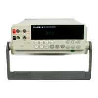
Fluke 45 Service Manual (184 pages)
Dual Display Multimeter
Brand:
Fluke
| Category:
Measuring Instruments
| Size: 4 MB
Table of Contents
Table of Contents
3
List of Tables
9
List of Figures
11
Introduction and Specifications
15
Introduction
15
Operating Instructions
15
Options and Accessories
15
Organization of the Service Manual
16
Conventions
17
Specifications
18
Theory of Operation
29
Introduction
31
Functional Block Description
31
Power Supply
31
Analog Measurement Processor
31
Input Protection Circuit
31
Input Signal Conditioning
31
Analog-To-Digital (A/D) Converter
31
Serial Communication (Guard Crossing)
31
Overall Functional Block Diagram
32
Digital Kernel
33
Display Assembly
33
IEEE-488 Interface Option (-05)
33
Battery Pack Option (-01)
33
Detailed Circuit Description
33
Power Supply Circuit Description
33
Raw DC Supply
34
5-Volt Switching Supply
34
Inverter
35
Analog Measurement Processor
35
Analog Simplified Schematic Diagram
36
Input Protection
38
Input Signal Conditioning
38
Relays
39
DC Volts
40
Ohms
40
DC Volts 300 V Range Simplified Schematic
40
Ohms Simplified Schematic
41
AC Volts
42
AC Buffer Simplified Schematic
42
Dcma
43
Acma
43
Amps
43
Diode/Continuity Test
43
Frequency
43
Active Filter
44
DC Ma and Amps Simplified Schematic
44
A/D Converter
45
Active Filter Simplified Schematic
45
Serial Communication (Guard Crossing)
46
Digital Kernel
46
A/D Converter Simplified Schematic
46
Interface
47
Microprocessor
47
Eerom
47
Ram
48
Rom
48
IEEE-488 Option Connections
48
Display Assembly
48
Main Assembly Connector
48
Front Panel Switches
48
Display
49
Beeper Drive Circuit
49
Watchdog Timer and Reset Circuit
49
Display Controller with FIP
50
Command Byte Transfer Waveforms
51
Grid-Anode Timing Relationships
52
General Maintenance
55
Introduction
57
Warranty Repairs and Shipping Information
57
General Maintenance Information
57
Required Equipment
57
Power Requirements
57
Static Safe Handling
57
Cleaning
58
Fuse Test and Replacement
58
Line Fuse
58
Current Input Fuses
58
Testing Current Input Fuses
58
Replacing the 500 Ma and 440 Ma Input Fuses (F1 and F5)
59
Replacing the Line Fuse (F3)
59
Replacing the 10 a Input Jack Fuse (F2)
60
Replacing the External 100 Ma Input Fuse (F1)
60
Disassembly Procedures
61
Remove the Meter Case
61
Remove Handle and Mounting Brackets
61
Removing the Case
61
Remove the Front Panel Assembly
62
Remove the Display PCA
62
Removing the Handle and Handle Mounting Brackets
62
Remove the IEEE-488 Option
63
Remove the Main PCA
63
Remove the Analog Measurement Processor Shields
63
Remove the Rms PCA
64
Remove the Battery Option
64
Disconnect Miscellaneous Chassis Components
64
Assembly Procedures
64
Install Miscellaneous Chassis Components
64
Install the Battery Option
65
Install the Rms PCA
65
Install the Analog Measurement Processor Shields
65
Install the Main PCA
65
Install the IEEE-488 Option
66
Assemble the Front Panel Assembly
66
Assembly Details
67
Install the Front Panel Assembly
69
Install the Handle and Mounting Brackets
69
Install the Meter Case
69
Performance Testing and Calibration
71
Introduction
73
Required Equipment
73
Performance Tests
74
Front Panel Calibration
77
Introduction
77
Entering Calibration Mode
78
Exiting Calibration Mode
79
DC Volts Calibration (Front Panel)
79
AC Volts Calibration (Front Panel)
79
DC and AC Milliamp Calibration (Front Panel)
79
DC and AC Amps Calibration (Front Panel)
81
Ohms Calibration (Front Panel)
81
Alternate Ohms Calibration (Front Panel)
83
Continuity/Hysteresis Threshold Calibration (Front Panel)
83
Frequency Calibration (Front Panel)
83
C2 Adjustment Procedure
83
Editing the Prompt for Different Calibration Points
84
C2 Location
84
Calibration Using the Computer Interface
85
Setup
85
Interface
85
IEEE-488 Interface
86
The Calibration Procedure
88
DC Volts Calibration (Computer Interface)
89
AC Volts Calibration (Computer Interface)
89
DC and AC Milliamps Calibration (Computer Interface)
89
DC and AC Amps Calibration (Computer Interface)
89
Ohms Calibration (Computer Interface)
89
Continuity/Hysteresis Threshold Calibration (Computer Interface)
90
Frequency Calibration (Computer Interface)
90
Concluding Calibration Using the Computer Interface
90
Alternate Ohms Calibration (Computer Interface)
90
Diagnostic Testing and Troubleshooting
93
Introduction
95
Servicing Surface-Mount Assemblies
95
Error Codes
96
Test Point Locator
99
General Troubleshooting Procedures
102
Power Supply Troubleshooting
102
Raw DC Supply
102
5-Volt Switching Supply
103
Inverter
104
Volt Switching Supply
104
Analog Troubleshooting
105
Uart Test
105
DC Volts Troubleshooting
106
AC Volts Troubleshooting
106
Ohms Troubleshooting
106
Digital Troubleshooting
107
Main Processor Timing
108
Display Assembly Troubleshooting
109
Display Controller to Microprocessor Signals
109
Calibration Failures
111
Introduction
111
Calibration-Related Components
112
Calibration Interrelationships
113
Retrieving Calibration Constants
113
Replacing the EEROM A1U5
113
List of Replaceable Parts
117
Introduction
119
How to Obtain Parts
119
How to Contact Fluke
120
Manual Status Information
120
Newer Instruments
120
Parts
120
Final Assembly
122
Option -01 Battery Pack
131
Introduction
133
Specifications
133
Theory of Operation
133
Functional Block Description
133
Battery Pack Option Functional Block Diagram
134
Switching Power Supply
135
Cycle/Float Charge Rate Switch
135
Low Battery Indicator Detector
135
Low Battery Disconnect
135
Constant Voltage Trickle Charger
136
Other Circuits
136
General Maintenance
136
Removal
136
Installation
137
Installing the Battery Kit
138
Performance Testing
139
General Operability
139
Battery Pack Option Connecting Cable
139
Low Battery Indicator Detector and Low Battery Disconnect Test
140
Cycle/Float Charge Rate Switch Test
140
Calibration
142
Troubleshooting
143
Unplugging the Battery Pack Connectors
143
Additional Tests
144
Schematic Diagram
144
List of Replaceable Parts
144
Test Points and Adjustments
144
A4 Battery Pack PCA
147
Option -05 IEEE-488 Interface
149
Introduction
151
Theory of Operation
151
Functional Block Description
151
Detailed Circuit Description
151
Main Assembly Connectors
151
Address Decoding Circuit
151
Isolation Circuits
152
IEEE-488 Controller
152
IEEE-488 Transceivers/Connector
153
IEEE-488 Interface Connector
155
General Maintenance
156
Removing the IEEE-488 Interface Option
156
IEEE-488 Module Assembly
156
Installing the IEEE-488 Interface Option
157
Performance Testing
157
Troubleshooting
158
Power-Up Problems
158
Communication Problems
158
Failure to Select IEEE-488 Interface Option
158
IEEE-488 Interface Performance Test
158
Failure to Handshake on IEEE-488 Bus
159
Failure to Enter Remote
159
Failure to Receive Multiple Character Commands
160
Failure to Transmit Query Responses
160
Failure to Generate an End or Identify (EOI)
160
Failure to Generate a Service Request (SRQ)
160
Schematic Diagram
160
List of Replaceable Parts
160
A5 IEEE-488 Interface PCA
162
Figure Title Page
165
A1 Main PCA
166
Schematic Diagrams
167
A1 Main PCA
167
A1 Main PCA
168
A2 Display PCA
172
Primary Display
173
Secondary Display
173
A2 Display PCA
173
A1A1 True Rms PCA
174
A1A1 True Rms PCA
175
A4 Battery PCA
176
A5 IEEE-488 Interface PCA
179
Advertisement
Fluke 45 User Manual (122 pages)
Dual Display Multimeter
Brand:
Fluke
| Category:
Multimeter
| Size: 2 MB
Table of Contents
Dual Display Multimeter
1
Limited Warranty and Limitation of Liability
2
Dual Display Multimeter
3
Table of Contents
5
List of Tables
9
Introduction
12
Introducing the Fluke 45 Dual Display Multimeter
12
Options and Accessories
13
Where to Go from here
13
Multimeter Safety
16
Getting Started
18
Introduction
18
Unpacking and Inspecting the Meter
18
Front Panel and Rear Panel
18
Adjusting the Handle
18
Line Power
18
Turning the Meter on
20
Using the Pushbuttons
20
Selecting a Measurement Range
22
Automatic Input Terminal Selection
22
Taking some Basic Measurements
22
Measuring Voltage, Resistance, or Frequency
23
Measuring Current
23
Diode/Continuity Testing
23
Operating the Meter under Battery Power (Optional)
26
Rack Mounting
26
Operating the Meter from the Front Panel
28
Introduction
28
Front Panel Operations
28
Display
29
Primary Display
29
Secondary Display
29
Input Terminals
31
Selecting a Measurement Function
32
Ranging
32
Autoranging
32
Manual Ranging
35
Measuring Frequency
35
Frequency Ranging
35
Frequency Measurement Rates
36
Measuring Frequency of Current (100 Ma and 10A) Inputs
36
Frequency Sensitivity Selection
36
Selecting a Function Modifier
37
REL (Relative Readings) Modifier
38
Db (Decibels and Audio Power) Modifier
39
HOLD (Touch Hold) Modifier
40
MN MX (Minimum Maximum) Modifier
40
Using Function Modifiers in Combination
40
Selecting a Measurement Rate (Rate)
41
Using the S Button
41
Using the Compare (Comp) Function
43
The List and Number Editors
43
Using the List Editor
44
Using the Number Editor
45
Power-Up Configuration
46
Factory Settings of Power-Up Configuration
46
Changing the Power-Up Configuration
46
Calibration
47
Applications
48
Introduction
48
Using the Dual Display
48
Using Measurement Functions in Combination
49
Taking Voltage and Current Measurements Using the Dual Display
49
Response Times
51
How the Meter Makes Dual Display Measurements
52
Updating the Primary and Secondary Displays with a Single Measurement
52
Updating the Primary and Secondary Displays with Separate Measurements
52
Update Rate in the Dual Display Mode
54
External Trigger
54
Thermal Voltages
55
When Measuring Resistance
56
Two-Wire Configuration
56
Correcting for Test Lead Resistance
56
True RMS Measurements
56
Effects of Internal Noise in AC Measurements
57
Calculated (AC + DC) RMS Measurements
57
Waveform Comparison (True RMS Vs. Average-Responding Meters)
57
Operating the Meter Using the Computer Interface
60
Introduction
60
Local and Remote Operations
60
Preparing the Meter for Operations Via the RS-232 Interface
61
Setting Communication Parameters (RS-232)
61
RS-232 Print-Only Mode
62
Cabling the Meter to a Host or Printer (RS-232)
63
Character Echoing and Deletion
63
Device Clear Using ^C (CNTRL C)
63
RS-232 Prompts
63
Preparing the Meter to be Operated Via IEEE-488 Interface
64
IEEE-488 Operating Limitations
64
Installing the IEEE-488 Interface
64
Enabling the IEEE-488 Interface
64
Addressing the Meter
64
Cabling the Meter to a Host
65
Getting Started with an Installation Test
65
Installation Test for RS-232 Operations
65
Installation Test for IEEE-488 Operations
65
If Test Fails
66
How the Meter Processes Input
66
Input Strings
66
Input Terminators
66
Typical IEEE-488 Input Strings
67
Sending Numeric Values to the Meter
67
Sending Command Strings to the Meter
67
How the Meter Processes Output
70
Triggering Output
70
External Triggering from the Front Panel
70
Setting the Trigger Type Configuration
71
External Triggering Via the Computer Interface
71
Service Requests
72
Output Queue
74
Event Status and Event Status Enable Registers
75
Status Byte Register
76
Reading the Status Byte Register
76
Service Request Enable Register
77
Computer Interface Command Set
78
IEEE-488 Capabilities and Common Commands
78
Function Commands and Queries
81
Function Modifier Commands and Queries
81
Range and Measurement Rate Commands and Queries
84
Measurement Queries
85
Compare Commands and Queries
86
Trigger Configuration Commands
86
Miscellaneous Commands and Queries
87
RS-232 Remote/Local Configurations
88
Sample Program Using the RS-232 Computer Interface
89
Sample Programs Using the IEEE-488 Computer Interface
90
Maintenance
95
Introduction
95
Cleaning
95
Line Fuse
95
Current Input Fuses
96
Testing Current Input Fuses
96
Replacing the 100 Ma Input Fuse
97
Replacing the 10 a Input Fuse
97
Self-Test Diagnostics and Error Codes
98
Performance Tests
98
Service
99
Replacement Parts
101
Appendices
103
A Specifications
103
BASCII/IEEE-488 Bus Codes
103
CIEEE-488.2 Device Documentation Requirements
103
Specifications
105
Input Protection
112
Advertisement
Related Products
Fluke 411D
Fluke Victoreen 451P
Fluke Victoreen 451P-DE-SI
Fluke RaySafe 452
Fluke 4588378
Fluke 4563561
Fluke 4534519
Fluke 4563577
Fluke COMARK 4902133
Fluke 43
Fluke Categories
Measuring Instruments
Test Equipment
Multimeter
Thermometer
Laboratory Equipment
More Fluke Manuals
Login
Sign In
OR
Sign in with Facebook
Sign in with Google
Upload manual
Upload from disk
Upload from URL