Sign In
Upload
Manuals
Brands
Fischer Panda Manuals
Inverter
14000
User Manuals: Fischer Panda 14000 Marine Generator
Manuals and User Guides for Fischer Panda 14000 Marine Generator. We have
1
Fischer Panda 14000 Marine Generator manual available for free PDF download: User Manual
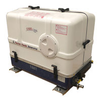
Fischer Panda 14000 User Manual (250 pages)
marine generator Panda Super silent technology 12000x PMS 12 kVA 230V - 50 Hz; Panda 15000x PMS 15 kVA 230V - 50 Hz
Brand:
Fischer Panda
| Category:
Inverter
| Size: 10 MB
Table of Contents
Current Revision Status
2
Table of Contents
3
1 General Instructions and Regulations
12
Safety First
12
Tools
16
Manufacturer Declaration in Accordance with the Machinery Directive 2006/42/EC
18
Customer Registration and Guarantee
18
Technical Support
18
Caution, Important Information for Start-Up
18
Safety Instructions - Safety First
19
Safe Operation
19
Observe Safety Instructions
19
Personal Protective Clothing (PPE)
19
Cleanliness Ensures Safety
19
Safe Handling of Fuels and Lubricants
20
Exhaust Fumes and Fire Protection
20
Safety Precautions against Burns and Battery Explosions
21
Protect Your Hands and Body from Rotating Parts
21
Anti-Freeze and Disposal of Fluids
21
Implementation of Safety Inspections and Maintenance
22
Warning and Instruction Signs
22
Special Instructions and Hazards of Generators
22
Protective Conductor and Potential Equalisation
23
Protective Conductor for Panda AC Generators
23
Switch off All Loads While Working on the Generator
23
Potential Equalisation for Panda AGT DC Generators
23
Safety Instructions Concerning Cables
24
Recommended Starter Battery Sizes
24
Important Instructions for Batteries - Starter And/Or Traction Batteries
24
General Safety Instructions for Handling Batteries
25
2 In Case of Emergency First Aid / IM Notfall - Erste Hilfe
27
When an Adult Stops Breathing
28
3 Basics
29
Intended Use of the Machine
29
Purpose of the Manual and Description of the Definitions of the Trained Persons/Operators/Users
29
Trained Persons
29
Operator
29
User
30
Components of the Xgenerator
30
Range of Operation
32
Panda Transport Box
32
Bolted Fischer Panda Transport Box
32
Fischer Panda Transport Box with Metal Tab Closure
32
Opening the MPL Sound Insulation Capsule
33
Opening the GFK Sound Insulation Capsule
34
Transport and Loading/Unloading
34
Transporting the Generator
34
Loading/Unloading of the Generator
34
Special Service Instructions and Measures for Extended Machine Downtimes and Decommissioning
35
Instructions for the Starter Battery for Extended Downtimes
35
Measures for Short Downtimes
36
Measures for Medium Term Downtimes / Hibernation
36
Courses for Preservation
36
Measures for Removing Surface Protection after Medium Term Downtimes
37
Months)
37
Measures for Extended Downtimes / Decommissioning
37
Courses for Preservation
37
Measures for Removing Surface Protection after Extended Downtimes / Recommissioning (over 6 Months)
38
4 The Panda Generator
39
Type Plate at the Generator
39
Description of the Generator
40
Right Side View
40
Left Side View
41
Font View
42
Back View
43
View from above
44
Details of Functional Units
45
Xcontrol Panel
45
The Cooling System - Schema
46
The Fuel System - Schema
47
The Operation Surveillance System
48
The Oil Circuit - Schema
50
Remote Control Panel - See Separate Control Panel Manual
50
Starting the Generator - See Separate Control Panel Manual
50
Stopping the Generator - See Separate Control Panel Manual
50
5 Generator Operation Instruction
51
Personal Requirements
51
Hazard Notes for the Operation
51
General Operating Instruction
51
Operation at Low Temperatures
51
Pre-Heating the Diesel Motor
52
Tips Regarding Starter Battery
52
Light Load Operation and Engine Idle
52
The Soot of the Generator Is Due to the Fact that
52
To Prevent the Soot of the Generator Following Steps Should be Observed
52
Generator Load for a Longer Period and Overload
52
Protection Conductor
53
Operating Control System on the Fischer Panda Generator
53
Instructions for Capacitors - Not Present at All Models
53
Checks before Start - See Remote Control Panel Data Sheet
53
Starting the Generator - See Remote Control Panel Data Sheet
54
Stopping the Generator - See Remote Control Panel Data Sheet
54
6 Installation Instructions
55
Personal Requirements
55
Hazard Notes for the Installation
55
Place of Installation
56
Preliminary Remark
56
Preparing the Base - Placement
57
Advice for Optimal Sound Insulation
57
Generator Connections
57
Installation of the Cooling System - Raw Water
58
General Information
58
Fischer Panda Installation Kit - Raw Water
58
Installation of the through Hull Fitting in Yachts - Scheme
60
Quality of the Raw Water Sucking in Line
60
Generator Installation above Waterline
60
Raw Water Installation Scheme
62
Generator Installation below Waterline
63
Raw Water Installation Scheme
64
Installation of the Cooling System - Fresh Water
65
Position of the External Cooling Water Expansion Tank
65
Scheme for Freshwater Circuit at Two Circuit Cooling System
66
Ventilation of the Coolant Circuit / Freshwater
66
Pressure Test for Controlling the Cooling Water Circuit
68
Installation of the Water Cooled Exhaust System
69
Fischer Panda Installation Kit - Exhaust System
69
Installation of the Standard Exhaust System
70
Installation of the Waterlock
71
Possible Cause for Water in the Exhaust Hose
72
Possible Cause: Exhaust Hose
72
Possible Cause: Cooling Water Hose
72
Installation Area of the Waterlock
72
The Volume of the Waterlock
73
Ideal Position of the Waterlock
75
Example of the Installation of the Waterlock Off-Center and Possible Effects
78
Exhaust / Water Separator
81
Installation Exhaust Water Separator
83
Installation of the Water Cooled Exhaust System
84
Installation of the Standard Exhaust System
84
Installation of the Waterlock
85
Possible Cause for Water in the Exhaust Hose
85
Possible Cause: Exhaust Hose
85
Possible Cause: Cooling Water Hose
85
Installation Area of the Waterlock
86
The Volume of the Waterlock
86
Ideal Position of the Waterlock
88
Example of the Installation of the Waterlock Off-Center and Possible Effects
91
Exhaust / Water Separator
94
Installation Exhaust Water Separator
96
Fuel System Installation
97
Fischer Panda Installation Kit - Fuel System
97
The Following Items Need to be Installed
99
Connection of the Fuel Lines at the Tank
101
Position of the Pre-Filter with Water Separator
102
Ventilating Air from the Fuel System
102
Generator DC System Installation
102
Connection of the Starter Battery Block
102
How to Connect Two 12 V Batteries to a 24 V Battery Bank
106
Connection of the Xcontrol Panel - See Separate Xcontrol Manual
107
Generator AC System Installation
107
AC-Control Box with VCS and Starting Current Limitation
107
Installation with Looped-In AC-Control Box
108
Installation AC-Box / Distribution Panel Connected Separately
109
Electronic Voltage Control Xcontrol
110
Connection to the AC On-Board Power Supply
110
Protective Conductor
110
Electrical Fuse
110
Required Cable Crosssections
110
Disconnector - Power Source Selector (Three Way Cam Switch)
110
Special Recommendations
111
Instructions on Prevention of Galvanic Corrosion
111
Instructions and Measures on Prevention of Galvanic Corrosion
111
Isolation Test
112
Initial Operation
112
7 Maintenance Instructions
113
Personal Requirements
113
Hazard Notes for the Maintenance
113
Environmental Protection
115
Maintenance Interval
115
General Maintenance Instructions
115
Checks before each Start
115
Check of Hoses and Rubber Parts in the Sound Insulated Capsule
115
Oil Change Intervals
116
Checking Oil-Level
116
Refilling Oil
117
After the Oil Level Check and Refilling the Oil
117
Replacement of Engine Oil and Engine Oil Filter
118
After the Oil Change
120
Verifying the Starter Battery and (if Necessary) the Battery Bank
121
Battery
121
Check Battery and Cable Connections
121
Check Electrolyte Level
121
Check Electrolyte Density
122
Grease Lubricated Generator Backend Bearing
122
Exchange of Grease Lubricated Bearing
123
Demounting the Cooling Disc (if Existent)
124
Demounting the Backend Bearing
124
Installing the New Backend Bearing
125
Checking the Oil Level of the Generator End Bearing at Fischer Panda Generators
128
Oil Level Check
129
Refilling Oil
129
Refiller-Set
130
Screw Plug
130
Replacement of the Oil-Cooled Backend Bearing
131
Exchange Oil-Cooled Bearing
131
Demounting the Bearing
131
Ventilating the Fuel System
143
Replacement of the Fuel Filter
144
Optional Fuel Filter with Sight Glass
145
Checking the Water Separator in the Fuel Supply
147
Replace the Air Filter Mat
147
Alternative Replacement of the Air Filter Mat with Pull out Holder
148
Alternative Replacement of the Air Filter at Housing with Snap Fasteners
150
Ventilation of the Coolant Circuit / Freshwater
151
V-Belt Replacement for the Internal Cooling Water Pump
153
The Raw Water Circuit
154
Clean Raw Water Filter
154
Causes with Frequent Impeller Waste
155
Replacement of the Impeller
156
Check and Discharge the Capacitors
157
Replacing the Electric Starter
159
Replacing the DC Alternator
162
Replacing the Oil Pressure Switch
166
Replacing the Oil Pressure Sensor (Optional Component)
167
Replacing the Injection Nozzles
168
Checking the Flame Glow Plug (Optional Unit)
171
Replacing the Flame Glow Plug
172
Replacing the Glow Plugs
173
8 Generator Faults
175
Personal Requirements
175
Hazard Notes for the Troubleshooting
175
Tools and Measuring Instruments
177
Troubleshooting Table and Flowchart
178
Generator Output Voltage too Low
178
Generator Voltage too High
178
Generator Voltage Fluctuates
178
Generator Not Able to Start Electric Motor
178
Diesel Motor Fails to Start
178
Starter Is Turning Motor, but Fails to Start
178
Motor Does Not Achieve Enough Speed During Starting Process
180
Motor Runs Unsteady
180
Motor Speed Drops
180
Motor Runs in off Position
180
Motor Stops by Itself
180
Sooty, Black Exhaust
181
Generator Must be Shut off Immediately if
181
Versions of the Generator Power Terminal Box
182
Overloading the Generator
186
Monitoring the Generator Voltage
187
Automatic Voltage Monitoring and Auto-Shut down
187
Generator-Output Voltage Is too Low
188
Check and Discharge the Capacitors
188
Checking the Capacitors
190
Checking the Electrical Connections to the Capacitors
190
Check the Generator Voltage
190
Measuring the Ohm Resistance of the Generator Windings
191
Check the Windings for Short Circuit
191
Measuring the Inductive Resistance
192
Generator Provides no Voltage
192
Rotor Magnetism Loss and „Re-Magnetising
192
Engine Starting Problems
193
Lifting Solenoid for Motor Stop - Optional
193
9 Tables
195
Technical Data
195
Rated Current
200
Cable Cross Section
200
Fuel
201
Engine Oil
201
Engine Oil Classification
201
Operating Range
201
Quality of Oil
201
Coolant Specifications
202
Coolant Mixture Ratio
202
Types of Coil
203
HP1 - 230V / 50 Hz
203
HP2 - 120V / 60 Hz
203
HP2 - 120V / 60 Hz - Duo
204
HP3 - 400V / 50 Hz
204
HP2 - 120V / 60 Hz
204
DVS - 400V / 50 Hz
205
DVS - 120V 240V / 60 Hz
205
Resistor & Inductance of the Generator Coil
205
Voltage Values Stator Coil
206
Diameter of Conduits
207
Current Revision Status
210
10 Safety Instructions Panda Xcontrol
211
Personal Requirements
211
Safety Instructions
211
11 Panda Xcontrol
213
Components of the Xcontrol
213
Xcontrol - CP-G
213
Xcontrol - GC-S
213
Xcontrol - CB-G
214
Installation
214
Installation of the Electronic Control Unit (ECU) Xcontrol - GC-S
214
Installation of the Connection Box Xcontrol - CB-G
214
Installation of the Xcontrol - CP-G
214
Operation
216
Switching on the Generator
216
Overview Screen with Activated Autostart
217
The Overview Screens
219
Overview Screens Symbolic
219
Overview Screens English Text
220
Overview Screens German Text
221
Start of the Generator
223
Marine Version Starting Preparation / Checks (Daily)
223
Vehicle Version Starting Preparation / Checks (Daily)
223
Starting the Generator
224
Stopping the Generator
225
The Menu
227
Main Menu
227
Submenu „Panel
228
Submenu „Generator
228
Set up the Brightness of the CP-G
228
Set up the Contrast of the CP-G
229
Set up the Standby Time out of the CP-G
229
Set up the Standby Brightness of the CP-G
230
Set up the Way of Illustration of the Overview Screens of the CP-G
230
Choose the Language of the Text Screens of the CP-G
231
Set up Temperature Unit
231
Reset All Values of the Panel Submenu to Standard
232
Back to the Main Menu
232
Submenu „Generator
233
Set up the Autostart of the CP-G
233
Set up the Optional DC Output of the CP-G
235
Set up the Operation Mode for the Opt. DC-Power (DP) Output of the CP-G
236
Set up the Follow-Up Time for the Opt. DP Output of the CP-G
236
Switch the Outputs of the CP-G
236
Check the Event Log of the CP-G
237
Reset All Values of the Generator Submenu to Standard
237
Back to the Main Menu
238
How to Change the Menu Text from German to English
238
Failure
239
Symbols and Messages in the Display
239
Message Sample „Sensor Defect
239
Message Sample Sensor/Cable Broken
239
Failure Code
240
Failuretable
240
Description of Symbols
242
Technical Data
244
Technical Data of the CB-G
244
Technical Data of the CP-G
245
Dimension Drawing
247
Advertisement
Advertisement
Related Products
Fischer Panda Panda AGT/DC 10000 PMS
Fischer Panda 12000
Fischer Panda 18
Fischer Panda 10000i
Fischer Panda 10000/9
Fischer Panda 10000x
Fischer Panda 15 mini PMS Digital
Fischer Panda Panda 10mini
Fischer Panda 15000i PVK-U
Fischer Panda 15000x PVMV-N
Fischer Panda Categories
Portable Generator
Inverter
Controller
Control Systems
Control Panel
More Fischer Panda Manuals
Login
Sign In
OR
Sign in with Facebook
Sign in with Google
Upload manual
Upload from disk
Upload from URL