Sign In
Upload
Manuals
Brands
Fastwel Manuals
Computer Hardware
CPC507
User Manuals: Fastwel CPC507 CompactPCI CPU Module
Manuals and User Guides for Fastwel CPC507 CompactPCI CPU Module. We have
2
Fastwel CPC507 CompactPCI CPU Module manuals available for free PDF download: User Manual
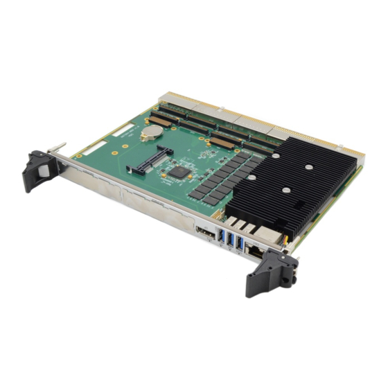
Fastwel CPC507 User Manual (55 pages)
SoC AMD FP5 APU Based 6U Compact PCI CPU Module
Brand:
Fastwel
| Category:
Computer Hardware
| Size: 1 MB
Table of Contents
Table of Contents
3
List of Tables
4
List of Figures
5
Conventions
7
General Rules of Usage
9
Manufacturer's Warranties
9
Transportation, Unpacking and Storage
11
Introductioin
13
System Overview
13
General Description of the Module
13
Module Versions
13
Table 1-1: Versions of CPC507
13
General Information
14
General Features of CPC507
14
Compatibility with the PICMG/VITA Standards
15
Device Dimensions
16
Delivery Checklist
16
Figure 2-1: Device Dimensions
16
Operational Conditions
17
Table 2-1: Delivery Checklist
17
Table 2-2: Operational Ranges of External Influencing Factors
17
Product Labeling
18
Packaging Information
18
Design and Operation
19
Block Diagram
19
Figure 3-1: Block Diagram of the Device
19
Specific Performance Features of Functional Nodes
20
System Expansion Options
21
PMC/XMC Modules
21
Using the Module in the CPCI System
21
Table 3-1: System Information
21
Location of Main Components
22
Figure 3-2: Location of the Main Components of CPC507
22
Intended Use
23
Module Interfaces
23
XMC Interface
23
Table 4-1: Purpose of XMC1 XS7 (P15) and XMC2 XS8 (P15) Connector Pins on the CPC507 Board
23
Figure 4-1: XMC XS7 (P15) and XS8 (P15) Connectors
23
PMC Interface
24
Figure 4-2: Connectors PMC XS10 (P3), XS11 (P1), XS12 (P3) and XS13 (P2)
24
Table 4-2: PMC Connector Pin Assignment
25
SATA Interface
26
Table 4-3: Assignment of SATA XS6 Connector Pins
26
COM Port
27
Connectors on the Front Panel of CPC507
27
Table 4-4: Assignment of XP2 Connector Pins
27
Figure 4-3: USB Connectors on the Front Panel of CPC507
27
Table 4-5: Assignment of USB Connector Pins on the Front Panel of CPC507
28
Table 4-6: Assignment of Gigabit Ethernet Connector Pins
28
Figure 4-4: Gigabit Ethernet RJ45 Connector
28
Table 4-7: Assignment of XS1 Displayport Connector Pins of the CPC507 Module
29
Figure 4-5: Displayport Connector
29
Leds on the Front Panel of CPC507
30
Using the Module in Compactpci System
30
Table 4-8: State of the SYS LED of the CPC507 Module
30
Figure 4-6: LEDS on the Front Panel of CPC507
30
Compact PCI Connectors
31
Figure 4-7: Compactpci Connectors (J1 - J5 in Accordance with the Compactpci Specification)
32
Table 4-9: Color Code Designations of Connectors
33
Table 4-10: Assignment of Pins of the Compactpci XS20 (J1) System Connector
33
Table 4-11: Pin Assignment of the XS18 (J2) System Connector of 64-Bit Compactpci Bus
34
Table 4-12: Pin Assignment of the XS21 (J3) Connector of CPC507
35
Table 4-13: Assignment of the XS19 (J4) Connector Pins of the CPC507 Module
36
Table 4-14: Assignment of the XS17 (J5) Connector Pins of CPC507
37
Timers
38
Watchdog Timer
38
Description of I/O Registers of WDT Controller
39
Table 4-15: Timer Current Value Register [23:0]
39
Table 4-16: Timer Initial Value Register [23:0]
39
Table 4-17: Status Register
40
Table 4-18: Control Register
40
SPI Controller / Leds / GPIO
41
Description of SPI Controller Registers
41
Table 4-19: Registers of the SPI Controller
41
Programming SPI Device
42
FRAM with Sequential Access
42
Devices on the Local Smbus
43
Battery
43
Table 4-20: Device Addresses on Smbus
43
Installation
44
Safety Requirements
44
CPC507 Installation Procedure
45
Board Removal Procedure
46
Installing Peripherals to CPC507
46
Connecting USB Devices
47
Battery Replacement
47
Installing Cfast Drive
47
System Setup
48
Resetting the BIOS Setup Settings
48
Ami Aptio Bios Setup
49
Starting and Updating BIOS Setup
49
Starting BIOS Setup
49
Navigation Keys
49
Table 7-1: Assignment of Navigation Keys
49
Figure 7-1: Assignment of Navigation Keys
49
BIOS Update
50
Advanced
51
Fastwel Features
51
Table 7-2: Setting the Fastwel Features
51
Cpc507 Troubleshooting
52
Table 8-1: Causes of Module Faults and Their Rectifications
52
Power Consumption
53
Table 9-1: Supply Voltage of +5 V,+3.3 V,+12 V,-12 V Fed from the CPCI Bus
53
Annex A: Terms, Acronyms and Abbreviations
54
Table a 1 - Terms, Acronyms and Abbreviations
54
Annex B: Dicslaimer
55
Advertisement
Fastwel CPC507 User Manual (60 pages)
3U CPCI Serial Elbrus CPU Module
Brand:
Fastwel
| Category:
Computer Hardware
| Size: 1 MB
Table of Contents
Table of Contents
3
List of Tables
4
List of Figures
5
Conventions
7
General Rules of Usage
9
Manufacturer's Warranties
9
Transportation, Unpacking and Storage
11
1 Introductioin
13
System Overview
13
General Description of the Module
13
2 General Information
14
General Features of CPC507
14
Compatibility with the PICMG/VITA Standards
16
Module Versions
16
Delivery Checklist
17
2.5 Packaging Information
17
2.6 System Expansion Options
17
2.7 System Information
17
Table 2 1: System Information
17
2.8 External View and Location of the Main Elements
18
Figure 1-1: Block Diagram of CPC507
19
Figure 2 2: Location of the Main Components of CPC507, Top View
20
Figure 2 3: CPC507: Size and Dimensions
21
3 Functional Description
22
3.1 Specific Performance Features of Functional Nodes
22
3.2 Module Interfaces
23
Table 3-1: Purpose of XMC1 XS7 (P15) and XMC2 XS8 (P15) Connectors Pins on the CPC507 Board
24
Figure 3-1: XMC XS7 (P15) and XS8 (P15) Connectors
24
Figure 3-2: Connectors PMC XS10 (P1), XS11 (P3), XS12 (P2) and XS13 (P4)
25
Table 3-2: PMC Connector Pin Assignment
26
Table 1-1: Assignment of SATA XS6 Connector Pins
27
Table 3-4: Assignment of XP2 Connector Pins
28
Figure 3-3: USB Connectors on the Front Panel of CPC507
28
Table 3-5: Assignment of USB Connector Pins on the Front Panel of CPC507
29
Table 3-6: Assignment of Gigabit Ethernet Connector Pins
29
Figure 3-4: Gigabit Ethernet RJ45 Connector
29
Table 3-7: Assignment of XS1 Displayport Connector Pins of the CPC507 Module
31
Figure 3-5: Displayport Connector
31
Table 3-8: State of the SYS LED of the CPC507 Module
32
Figure 3-6: LEDS on the Front Panel of CPC507
32
Figure 3-7: Compactpci Connectors (J1 - J5 in Accordance with the Compactpci Specification)
34
Table 3-9: Color Code Designations of Connectors
35
Table 1-2: Assignment of Pins of the Compactpci XS20 System Connector (J1)
36
Table 1-3: Pin Assignment of the XS18 (J2) System Connector of 64-Bit Compactpci Bus
37
Table 1-4: Pin Assignment of the XS21 (J3) Connector of CPC507
38
Table 3-13: Assignment of the XS19 (J4) Connector Pins of the CPC507 Module
39
Table 3-14: Assignment of the XS17 (J5) Connector Pins of CPC507
40
Timers
41
SPI Controller / Leds / GPIO
44
Table 3-15: Registers of the SPI Controller
44
Devices on the Local Smbus
46
Battery
46
NAND Drive
46
Table 3-16: Device Addresses on Smbus
46
4 Installation
47
Safety Requirements
47
CPC507 Installation Procedure
48
Board Removal Procedure
49
Installing Peripherals to CPC507
49
Battery Replacement
50
Installing Cfast Drive
50
5 System Setup
51
Resetting the BIOS Setup Settings
51
6 Ami Aptio Bios Setup
52
Starting and Updating BIOS Setup
52
Figure 6-1: Assignment of Navigation Keys
52
Advanced
54
7 Troubleshooting
55
Table 7 1: CPC507 Fault Causes and Their Rectifications
55
8 Power Consumption
56
Table 8 1: Supply Voltage of +5 V,+3.3 V,+12 V,-12 V Fed from the CPCI Bus
56
9 Influence of External Factors
57
CPC507 Operating Conditions and MTBF
57
Table 9 1: Influence of External Factors During Operation of CPC507
57
Annex A: Terms, Acronyms and Abbreviations
58
Table a 1 - Terms, Acronyms and Abbreviations
58
Annex B: Dicslaimer
60
Advertisement
Related Products
Fastwel CPC514
Fastwel CPC1001
Fastwel CPC307-01
Fastwel CPC307-02
Fastwel CPC307-03
Fastwel CPC307-04
Fastwel CPC307-05
Fastwel CPC505
Fastwel CPC314
Fastwel CPC522
Fastwel Categories
Control Unit
Computer Hardware
Motherboard
Processor
Single board computers
More Fastwel Manuals
Login
Sign In
OR
Sign in with Facebook
Sign in with Google
Upload manual
Upload from disk
Upload from URL