
Related Manuals for Fastwel CPC507


Summary of Contents for Fastwel CPC507
- Page 1 CPC507 SoC AMD FP5 APU Based 6U Compact PCI CPU Module User Manual Rev. 002 August 2022 The product described in this manual is compliant with all related CE standards.
- Page 2 Product Title: CPC507 Document name: CPC507 User Manual Manual version: 002 Ref. docs: Copyright © 2022 Fastwel Co. Ltd. All rights reserved. Revision Record Rev. Index Brief Description Product Index Date Initial version CPC507 February 2021 Compliance assessment CPC507 August 2022 Contact Information Fastwel Co.
-
Page 3: Table Of Contents
4.1.1 XMC interface………………………………………………………………………………………………………..21 4.1.2 PMC interface………………………………………………………………………………………………………..22 4.1.3 SATA interface………………………………………………………………………………………………………24 4.1.4 COM port…………………………………………………………………………………………………………..…25 4.1.5 Connectors on the front panel of CPC507…………………………………………………………………….…25 4.1.6 LEDs on the front panel of CPC507……………………………………………………………………………..28 4.1.7 Using the module in CompactPCI system………………………………………………………………………..28 4.1.8 Compact PCI connectors…………………………………………………………………………………………..29 4.2 Timers ………………………………………………………………...……………………………………………………36 4.2.1 Watchdog Timer…………………………………………………………………………………………………….36... -
Page 4: List Of Tables
Table 2-2: Operational ranges of external influencing factors …………………………………………………………….15 Table 3-1: System information …………………………………………………………………………………………………...19 Table 4-1: Purpose of XMC1 XS7 (P15) and XMC2 XS8 (P15) connector pins on the CPC507 board …….………...21 Table 4-2: PMC connector pin assignment ………………………………………..…………………………………………..23 Table 4-3: Assignment of SATA XS6 connector pins ……..…………………………………………………………………24 Table 4-4: Assignment of XP2 connector pins …………………………………………..……………………………………25... -
Page 5: List Of Figures
This document contains information, which is property of Fastwel Co. Ltd. It is not allowed to reproduce it or transmit by any means, to translate the document or to convert it to any electronic form in full or in parts without antecedent written approval of Fastwel Co. Ltd. or one of its officially authorized agents. - Page 6 CPC507 Ownership rights This document contains information that is the property of Fastwel Group. It may not be copied or transmitted by any known means, nor may it be stored in information storage and retrieval systems without the prior written consent of Fastwel Group or one of its authorized agents. The information...
-
Page 7: Conventions
CPC507 Conventions Caution, High Voltage! This sign and text warn of the dangers associated with electrical discharges (> 60 V) when touching the device or any part of it. Failure to follow the precautions mentioned or prescribed in the regulations may endanger your life or health, and may result in damages to the equipment. - Page 8 CPC507 Safety requirements This Fastwel Group product has been developed and tested to ensure compliance with electrical safety requirements. Its design provides long-term failsafe operation. Mishandling the product during unpacking and installation may significantly affect the product's life cycle. Therefore, for your own safety and for ensuring proper operation of the device, you should follow the recommendations given below.
-
Page 9: General Rules Of Usage
Fastwel Group other than those contained in this User Manual or received from the technical support service of Fastwel Group in the form of a set of instructions for their implementation will void the warranty. - Page 10 CPC507 Limitation of warranty obligations The above warranty does not apply to: - the products (including software) that have been repaired or modified by the employees who do not represent the Manufacturer. The exception is when the Consumer has made repairs or made changes to the product strictly in accordance with the instructions previously agreed and approved by the Manufacturer in writing;...
-
Page 11: Transportation, Unpacking And Storage
CPC507 Transportation, Unpacking and Storage Transportation The modules should be transported in the separate manufacturer’s packaging (container), consisting of an individual antistatic packaging and a cardboard box, in closed transport (road, rail, air in heated and sealed compartments) under storage conditions 5 according to the GOST standard 15150-69 or under storage conditions 3 for sea transportation. - Page 12 If a product should fail through Fastwel's fault during the warranty period, it will be repaired free of charge. For out of warranty repairs, the customer will be invoiced for repair charges at current standard labor and materials rates.
-
Page 13: Introductioin
The CPC507 CPU module, implemented in accordance with the 6U CompactPCI standard, expands the line of Fastwel 6U modules. The most important feature of this module is the availability of two platforms for installation of PMC / XMC mezzanine modules. By using a single- chip solution based on AMD FP5 APU (Ryzen Embedded V-Series) SoC, together with 2 mezzanine modules, CPC507 can be used in compact and cost-effective computing systems. -
Page 14: General Information
- 8 x graphics cores; - 6 MB cache; ● RAM: ◦ DDR4-2400 SDRAM with ECC support: - 16 GB (for CPC507-01); - 8 GB (for CPC507-02). ● Video Output: - DisplayPort (4096x2160@60Hz) interface, routed to the front panel; ● PCI Bus: - Routed to the CompactPCI J1/J2 connectors;... -
Page 15: Compatibility With The Picmg/Vita Standards
● MTBF: - Min. 50,000 hours; Compatibility with the PICMG/VITA standards The CPC507 module is compatible with the following PICMG/VITA standards: - PICMG 2.0 CompactPCI R3.0 Specification; - PICMG 2.3 PMC on CompactPCI R1.0 Specification; - PICMG 2.16 CompactPCI Packet Switching Backplane R1.0 Specification;... -
Page 16: Device Dimensions
CPC507 2.3. Device dimensions Figure 2-1: Device dimensions 2.4. Delivery checklist The complete delivery checklist for CPC507 is specified in the Table 1-2. C P C 5 0 7 . U s e r M a n u a l... -
Page 17: Operational Conditions
CPC507 Table 2-1: Delivery checklist Designation Name Number Note IMES.467444.117 CPC507-01 CPU Module 1 pcs. IMES.467444.117-01 CPC507-02 CPU Module An installation kit consisting of: IMES.467941.057 1 pcs. - locking mechanism IMES.741124.233 - 1 pcs; - screw DIN7985-M2,5x6-A2 - 2 pcs. -
Page 18: Product Labeling
- Product version; - Factory number of the product. 2.7 Packaging information The CPC507 Module is supplied in a box of the following size: 350х260х70 mm. Packaged weight of the device – no more than 0.8 kg. Note Keep the module’s anti-static bag and consumer packaging in their original form until the end of the warranty period. -
Page 19: Design And Operation
CPC507 3 Design and operation 3.1 Block diagram The block diagram is specified in Figure 3-1 below. Fig. 3-1 – Block diagram of the device C P C 5 0 7 . U s e r M a n u a l... -
Page 20: Specific Performance Features Of Functional Nodes
CPC507 3.2 Specific performance features of functional nodes AMD Ryzen Embedded SoC APU 64-bit AMD CPU, manufactured on 14nm technology node, offering TDP of 25W and an industrial operating temperature range (from -40 to + 105°C). This CPU is a single-chip solution that combines 4 x AMD “Zen” processing cores, a 64-bit dual-... -
Page 21: System Expansion Options
Jumpers The board has a switch for resetting BIOS to default settings. 3.3 System expansion options The number of interfaces routed from the CPC507 module can be increased by installing 2 x XMC/PMC expansion modules. 3.3.1 PMC/XMC Modules PMC/XMC interface of the CPC507 board supports two expansion modules of the XMC/PMC standard, which ensures an easy and flexible adaptation of CPC507 in accordance with the requirements of various applications. -
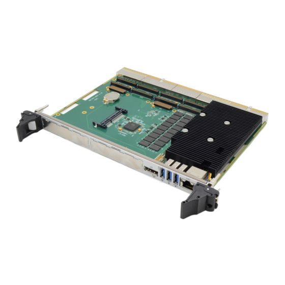
Page 22: Location Of Main Components
CPC507 Location of main components Figure 3-2: Location of the main components of CPC507 The appearance of the module versions may slightly differ from the one shown in this figure. C P C 5 0 7 . U s e r... -
Page 23: Intended Use
XS8 (P15) connectors. Figure 4-1: XMC XS7 (P15) and XS8 (P15) connectors Below you can find the pinout tables for XMC connectors. Table 4-1: Purpose of XMC1 XS7 (P15) and XMC2 XS8 (P15) connector pins on the CPC507 board RX0+ RX0- +3.3V... -
Page 24: Pmc Interface
J5 and J3 CompactPCI connectors. The PMC interface complies with the ANSI/VITA 39 specification, which defines the PCI-X electrical interface for the boards of the Common Mezzanine Card (CMC) form-factor. CPC507 allows operation of the 3.3V PCI bus. -
Page 25: Table 4-2: Pmc Connector Pin Assignment
CPC507 Table 4-2: PMC connector pin assignment Number of pin Number of pin Number of pin Number of XS9(P1)/XS11( XS10(P3)/XS12 XS13(P2)/XS Function Function Function (P3) 15(P2) XS14(P4)/ Function XS16(P4) P1_1 P2_1 +12V P3_1 P4_1 PMC_I/O P1_2 -12V P2_2 P3_2 P4_2... -
Page 26: Sata Interface
(XS6); the second interface is used for connection of the integrated SSD. The XS6 connector (located on the top side of the CPC507 board, see Figure 3-2: Location of the main components of CPC507) enables installing a CFast drive on the CPC507 module together with the PMC/XMC expansion module. -
Page 27: Com Port
4.1.5 Connectors on the front panel of CPC507 4.1.5.1 USB interfaces CPC507 has 3 x USB3.1 Gen 1 ports located on the front panel. The following modes are supported: high-speed, full-speed, and low-speed. USB 2.0 in the high-speed mode enables data transfer at the rates up to 480 Mb/sec, USB 3.1 Gen1 - up to 5 Gb/sec. -
Page 28: Table 4-5: Assignment Of Usb Connector Pins On The Front Panel Of Cpc507
CPC507 Table 4-5: Assignment of USB connector pins on the front panel of CPC507 Circuit Function VBus +5V Power USB D- Differential USB- USB D+ Differential USB+ Ground for power return StdA_SSRX- SuperSpeed RX- StdA_SSRX+ SuperSpeed RX+ GND_DRAIN Ground for signal return... -
Page 29: Table 4-7: Assignment Of Xs1 Displayport Connector Pins Of The Cpc507 Module
4.1.5.3 DisplayPort The DisplayPort connector on the front panel of the CPC507 is designed for connecting digital monitors with resolution up to 4096x2160@60Hz. The output also makes it possible to connect DVI-D monitors via a passive adapter and VGA and other monitor types via an active adapter. -
Page 30: Leds On The Front Panel Of Cpc507
4.1.7 Using the module in CompactPCI system The CPC507 module has a flexible CompactPCI interface. If the board is installed into the system slot, then the PCIE-PCI bridge operates in the PCI bus master mode, and if the board is installed into the peripheral slot, the bridge operates in the “non-transparent”... -
Page 31: Compact Pci Connectors
CPC507 4.1.7.3 Packet Switching Backplane PICMG 2.16 2 x Gigabit Ethernet ports are available on the XS21 connector of the device in accordance with the PICMG specification for CompactPCI Packet Switching Backplane Specification PICMG 2.16, version 1.0. By the CompactPCI Packet Switching Backplane these ports are connected with special-purpose Ethernet hub fabric slots. -
Page 32: Figure 4-7: Compactpci Connectors (J1 - J5 In Accordance With The Compactpci Specification)
CPC507 Figure 4-7: CompactPCI connectors (J1 – J5 in accordance with the CompactPCI specification) 4.1.8.1 Color code designations of CompactPCI connectors The CompactPCI connectors use guide lugs in order to ensure proper connection. To avoid wiring errors, color coding is also used for the various standard operating voltages. The color coding prevents 5V peripheral cards from being mounted into the sockets designed for 3.3V voltage, and... -
Page 33: Table 4-9: Color Code Designations Of Connectors
(5 V and 3.3 V) 4.1.8.2 Pin assignment of CompactPCI XS20 and XS18 connectors CPC507 is equipped with 2 CompactPCI bus connectors, where the pins have a pitch of 22 mm – XS20 and XS18. Table 4-10: Assignment of pins of the CompactPCI XS20 (J1) system connector... -
Page 34: Table 4-11: Pin Assignment Of The Xs18 (J2) System Connector Of 64-Bit Compactpci Bus
4.1.8.3 I/O CompactPCI XS21, XS19, XS17 connectors (J3 - J5) and their pin assignment In CPC507, part of the I/O signals are routed to the XS21, XS19 and XS17 connectors. A special backplane is required for using Rear I/O modules. The XS21, XS19 and XS17 connectors of the board are compatible with all standard 6U CompactPCI backplanes with I/O support through the corresponding connectors in the system slot. -
Page 35: Table 4-12: Pin Assignment Of The Xs21 (J3) Connector Of Cpc507
CPC507 Table 4-12: Pin assignment of the XS21 (J3) connector of CPC507 XS21 +VI/O PMC2_IO63 PMC2_IO62 PMC2_IO61 PMC2_IO60 PMC2_IO59 PMC2_IO58 PMC2_IO57 PMC2_IO56 PMC2_IO55 PMC2_IO54 PMC2_IO53 PMC2_IO52 PMC2_IO51 PMC2_IO50 PMC2_IO49 PMC2_IO48 PMC2_IO47 PMC2_IO46 PMC2_IO45 PMC2_IO44 PMC2_IO43 PMC2_IO42 PMC2_IO41 PMC2_IO40 PMC2_IO39 PMC2_IO38... -
Page 36: Table 4-13: Assignment Of The Xs19 (J4) Connector Pins Of The Cpc507 Module
CPC507 Table 4-13: Assignment of the XS19 (J4) connector pins of the CPC507 module XS19 DP1_HPD DP1_LANE0+ DP1_LANE0- LAN_LED0 DP1_LANE1+ DP1_LANE1- LAN_LED1 DP1_LANE2+ DP1_LANE2- LAN_LED2 DP1_LANE3+ DP1_LANE3- LAN_LED3 DP1_AUX- DP1_AUX+ DP_CTRL_DAT DP2_HPD DP3_LANE0+ DP3_LANE0- DP2_LANE0+ DP2_LANE0- DP3_LANE1+ DP3_LANE1- DP2_LANE1+ DP2_LANE1-... -
Page 37: Table 4-14: Assignment Of The Xs17 (J5) Connector Pins Of Cpc507
CPC507 Table 4-14: Assignment of the XS17 (J5) connector pins of CPC507 XS17 LPC_AD0 LPCCLK +3,3V LPC_AD1 SIOCLK +3,3V LPC_AD2 SUSCLK +3,3V USB1_DP USB1_DM LPC_AD3 SERIRQ USB3_DP USB3_DM LPC_FRAME# LPC_RST# USB0_DP USB0_DM ETH_MDI1+ ETH_MDI1- ETH_MDI3+ ETH_MDI3- ETH_MDI0+ ETH_MDI0- ETH_MDI2+ ETH_MDI2-... -
Page 38: Timers
CPC507 4.2 Timers The module is equipped with the following timers: RTC (Real-Time Clock) PCH includes a battery powered real time clock. Watchdog Timer See the description below. 4.2.1 Watchdog Timer The watchdog timer is implemented in the FPGA as a device based on the LPC bus. The watchdog timer is enabled and the hardware interrupt (IRQ) is selected in the BIOS Setup. -
Page 39: Description Of I/O Registers Of Wdt Controller
CPC507 4.2.2 Description of I/O registers of WDT controller Table 4-15: Timer Current Value Register [23:0] Base+0h Name Description Write/Read: Timer_Current_Value[7:0] Bits 7:0 of the counter initial value Base+1h Name Description Write/Read: Timer_Current_Value[15:8] Bits 15:8 of the counter initial value... -
Page 40: Table 4-17: Status Register
CPC507 Table 4-17: Status Register Base+6h Name Description Reserved Write/Read: Second timeout flag. It is set to “1” if TMF = 1. This flag initiates an interrupt. If the board reset is enabled RSTE = 1, a hardware reset is carried out. Can be reset by writing “1”... -
Page 41: Spi Controller / Leds / Gpio
CPC507 4.3 SPI controller / LEDs / GPIO 4.3.1 Description of SPI controller registers Table 4-19: Registers of the SPI controller I/O port address Type HARD RESET Configuration register Base+0 FRAM address value [7:0] Base+1 FRAM address value [14:8] Base+2... -
Page 42: Programming Spi Device
CPC507 4.3.2 Programming SPI device The work with FRAM is carried out in the I/O area at addresses 310h-313h. Writing data byte (32h) to FRAM at the address (144h) DX, 310H AL, 44H DX, AL DX, 311H AL, 01H... -
Page 43: Devices On The Local Smbus
PCI-E Bridge PMC 4.5 Battery The CPC507 uses one 3.0 V lithium battery to power the real time clock. In case of prolonged use of the module in temperatures below -20C°, it is recommended to use an external clock synchronization (e.g. via NTP protocol) and to save all necessary BIOS settings as defaults. For details, see the section "Replacing the battery". -
Page 44: Installation
Please refer to the documentation attached to your operating system. Safety requirements When handling CPC507, you should strictly follow the safety requirements listed below. The manufacturer – Fastwel Group, shall not be responsible for any damages resulting from noncompliance with these requirements. -
Page 45: Cpc507 Installation Procedure
CPC507 installation procedure The below procedure refers to the installing the CPC507 into the system. The removal procedure is described in other subparagraphs. In order to install the board into the system, follow the below procedure: Make sure that the safety requirements listed in subparagraph 5.1 have been observed. -
Page 46: Board Removal Procedure
Installing peripherals to CPC507 A wide range of peripheral devices can be connected to the CPC507, where their installation methods can vary greatly. The following sections contain general installation instructions rather than detailed algorithms. -
Page 47: Connecting Usb Devices
CPC507 5.4.1 Connecting USB devices CPC507 supports any Plug & Play USB computer peripherals (e.g. drive, keyboard, mouse, printer, etc.). Note All USB devices can be connected and disconnected while the power of these devices and the head system is on. -
Page 48: System Setup
CPC507) is designed to reset the BIOS settings to the state specified by the manufacturer (factory defaults) if the system does not boot (e.g. due to the BIOS setup errors or invalid password). In order to reset the BIOS parameters of the CPC507 module, the sequence of actions should be as follows: De-energize the system;... -
Page 49: Ami Aptio Bios Setup
CPC507 AMI Aptio BIOS Setup Starting and Updating BIOS Setup An adapted version of the Aptio TSE (Text Setup Environment) BIOS is installed on your computer, which is the standard system for IBM PC AT-compatible computers. It supports Intel® x86 and compatible processors and provides low-level support for processor, memory, and I/O subsystems. -
Page 50: Bios Update
CPC507 Using this key the user can load the previous value into TSE. With this key, the user can load the optimum default settings into TSE. With this key, user can save current settings and exit the TSE. The <ESC> key enables you to discard the changes made and exit Aptio TSE. -
Page 51: Advanced
CPC507 Advanced The tab is used for making additional module settings. 7.2.1 Fastwel Features This tab is used for configuring module’s devices. Table 7-2: Setting the Fastwel Features Function Purpose Default value Operation mode of the board’s Ejector switch function... -
Page 52: Cpc507 Troubleshooting
CPC507 CPC507 Troubleshooting Before contacting the service center, please read the troubleshooting information, since the problem may not be related to the device failure. Table 8-1: Causes of module faults and their rectifications Issue Cause Rectification The board does not... -
Page 53: Power Consumption
CPC507 Power Consumption The CPC507 module is designed with due consideration of the optimum power consumption and distribution. However, we should pay attention to certain requirements that are vital to ensure stability and reliability. The table below shows the values of the maximum allowable voltages on the power lines, which, if exceeded, can result in module damages. -
Page 54: Annex A: Terms, Acronyms And Abbreviations
CPC507 ANNEX A Table A 1 – Terms, acronyms and abbreviations Term Value BIOS Basic Input-Output System cPCI CompactPCI DDR SDRAM Double Data Rate Synchronous Dynamic Random Access Memory Error Correction Code EIDE Enhanced Integrated Drive Electronics GPIO General Purpose Input Output. -
Page 55: Annex B: Dicslaimer
1.2 Use of the Fastwel products as well as the objects of intellectual property containing in them, in the ways and for the purposes, not provided by the present user manual and datasheet isn't allowed without preliminary written approval of Fastwel.
Need help?
Do you have a question about the CPC507 and is the answer not in the manual?
Questions and answers