Sign In
Upload
Manuals
Brands
Fastwel Manuals
Computer Hardware
CPC307-04
Fastwel CPC307-04 Manuals
Manuals and User Guides for Fastwel CPC307-04. We have
1
Fastwel CPC307-04 manual available for free PDF download: User Manual
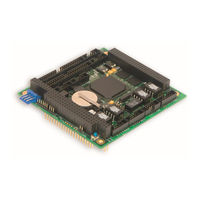
Fastwel CPC307-04 User Manual (75 pages)
PC/104-Plus Vortex86DX Based CPU Module
Brand:
Fastwel
| Category:
Motherboard
| Size: 2.84 MB
Table of Contents
User Manual
1
Table of Contents
3
List of Tables
5
List of Figures
6
Notation Conventions
7
General Safety Precautions
8
Unpacking, Inspection and Handling
9
Three Year Warranty
10
1 Introduction
11
Module Introduction
11
CPC307 Versions
12
Table 1.1: CPC307 Versions
12
Delivery Checklist
13
Additional Accessories
13
Table 1.2: CPC307 Supplied Set
13
Table 1.3: CPC307 Additional Accessories
13
2 Technical Specifications
15
General
15
Power Requirements
17
Environmental
17
Mechanical
17
Table 2.1: Power Supply Requirements
17
Dimensions and Weight
18
Mtbf
18
3 Functional Description
19
Structure and Layout
19
Figure 3.1: CPC307 Block Diagram
19
Figure 3.2: Top Side: Connectors and Main Components Layout
21
Figure 3.3: Bottom Side: Connectors and Main Components Layout (CPC30704)
22
Functional Description
23
Vortex86Dx Soc
23
Figure 3.4: Vortex86Dx Soc Block Diagram
23
SDRAM Memory
24
IDE Interface
24
Table 3.1: IDE Channel: Devices Connection Variants
24
Table 3.2: XP13 Connector Pinout (IDE)
24
Figure 3.5: XP13 IDC44 Pins Numbering
24
Microsd
25
ATA Flash Disk
25
Table 3.3: XS3 and XS4 Microsd Sockets Pinout
25
Figure 3.6: Microsd Cards Contacts Numbering
25
PS/2 Keyboard and Mouse Interface
26
Optoisolated Reset/Irq Input
26
Table 3.4: XP23 Contacts Designation
26
Figure 3.7: XP23 Connector Contacts Numbering
26
Figure 3.8: XP19 Connector
26
Figure 3.9: Discrete Input Optoisolation and Reset or IRQ Source Selection
26
USB Interface
28
Table 3.5: XP12 Connector Pinout (USB)
28
Figure 3.10: Xp12Connector
28
Fast Ethernet Interface
29
Serial Ports
29
COM1 and COM2
29
Table 3.6: XP9 Ethernet Header Pinout
29
Figure 3.11: XP9 Connector
29
Figure 3.12: IDC10 Pins Numbering
29
Table 3.7: XP18 Pinpad Jumpers
30
Figure 3.13: XP18 Pinpad
30
Table 3.8: XP10 and XP16 Pin Assignments
31
Figure 3.14: RS485/422 Transmitter with Bias Elements and Terminating Resistors
31
Figure 3.15: Connection of Several Devices in RS422 Mode
32
Figure 3.16: Connection of Several Devices in RS485 Mode
32
COM3 and COM4
33
COM5 and COM6
33
Table 3.9: XP6 and XP7 Pin Assignments
33
Table 3.10: COM5 and COM6 Controllers Resources
33
Table 3.11: XP15 and XP20 Pinpads Jumpers
34
Figure 3.17: XP15 and XP20 Pinpads
34
Figure 3.18: Transmitter with Protective Bias Elements and Terminating Resistors
34
Parallel Printer Port (LPT)
35
Table 3.12: XP17 Pin Assignments (COM5 and COM6)
35
Table 3.13: XP12 (LPT) Connector Pinout
35
Figure 3.19: XP12 Connector
35
Expansion Buses: ISA and PCI
36
PCI Header
36
Table 3.14: XS1 Connector Contacts Designation (Rows A, B)
36
Figure 3.20: XS1 Connector Contacts Layout
36
Table 3.15: XS1 Connector Contacts Designation (Rows C, D)
37
ISA Header
38
Table 3.16: ISA XS2 Connector (Rows a and B) Contacts Designation
38
Figure 3.21: ISA Header Contacts Layout
38
Table 3.17: ISA XS2 (Rows C and D) Contacts Designation
39
Redundancy
40
Figure 3.22: Redundancy Pinpads Connection
40
Figure 3.23: XP11 Pinpad
40
CAN Ports
41
Table 3.18: XP11 Pinout (CPC307-01)
41
Table 3.19: CAN Controllers Addresses
41
Table 3.20: XP4 and XP8 Pinpads Jumpers
41
Figure 3.24: XP4 and XP8 Pinpads
41
Figure 3.25: XP5 Pins Numbering (CAN)
41
Watchdog Timers
42
RTC, CMOS, Serial FRAM and Reserved BIOS
42
Reserved BIOS
42
Table 3.21: XP5 Connector Pinout (CAN)
42
RTC, CMOS and Battery
43
Fram
43
BIOS Upgrade
43
Power Supply
43
Figure 3.26: XP22 Power Supply Connector
43
Power Supply Supervisor
44
Table 3.22: XP22 Power Connector Pinout
44
Figure 3.27: Power Supply Supervisor Diagram
44
GPIO Ports
45
Configuration Jumpers
45
Diagnostic Leds
45
Table 3.23: CPC307 Diagnostic Leds Function
45
Table 3.24: XP3 Contacts Function
45
Reset Button
46
Address Mapping
46
Memory Addressing
46
I/O Addressing
46
Table 3.25: Memory Address Mapping
46
Table 3.26: I/O Address Space
46
Figure 3.28: External Leds Connection (XP3)
46
Integrated Address Decoder
48
CAN Ports Addresses
48
COM5 and COM6 Ports Addresses
48
Interrupt Settings
49
Table 3.27: Interrupt Settings
49
DMA Channels
50
Table 3.28: DMA Channels
50
Overall and Mounting Dimensions
51
Figure 3.29: CPC307: Overall and Mounting Dimensions
51
4 External Connections
52
Safety Regulations
52
Connection of Peripheral Devices
53
Software Installation
53
Figure 4.1: External Devices Connection
53
5 Ami Bios
54
BIOS Setup Program. Introduction
54
Main Menu
54
Table 5.1: Main Menu Items
55
Figure 5.1: Main Menu Screen Image
55
Advanced
56
Figure 5.2: Advanced Screen Image
56
Table 5.2: Advanced Menu Items
56
CPU Configuration
57
Figure 5.3: CPU Configuration Menu Screen
57
Table 5.3: CPU Configuration Menu Items
57
Figure 5.4: IDE Configuration Menu Screen
58
IDE Configuration
58
Table 5.4: IDE Configuration Menu Items
58
Figure 5.5: Primary IDE Master Menu Screen
59
Table 5.5: Primary IDE Master Menu Items
59
Figure 5.6: Remote Access Configuration Menu Screen
60
Remote Access Configuration
60
Table 5.6: Remote Access Configuration Menu Items
61
Figure 5.7: USB Configuration Menu Screen
62
Table 5.7: Name
62
USB Configuration
62
PCI Plug and Play
63
Table 5.8: PCI Plug and Play Menu Items
63
Figure 5.8: PCI Plug and Play Menu Screen
63
Boot Options
65
Figure 5.9: Boot Menu Screen
65
Table 5.9: Boot Menu Items
65
Boot Settings Configuration
66
Figure 5.10: Boot Settings Configuration Menu Screen
66
Table 5.10: Boot Settings Configuration Menu Items
66
Security Options
67
Table 5.11: Security Menu Items
67
Figure 5.11: Security Menu Screen
67
Chipset Menu
68
Figure 5.12: Chipset Menu Screen Image
68
Table 5.12: Chipset Menu Items
68
Figure 5.13: North Bridge Configuration Menu Screen
69
North Bridge Configuration
69
Table 5.13: North Bridge Configuration Menu Items
69
Figure 5.14: South Bridge Configuration Menu Screen
70
South Bridge Configuration
70
Table 5.14: South Bridge Configuration Menu Items
70
Exit Menu
71
Table 5.15: Exit Menu Items
71
Figure 5.15: Exit Menu Screen Image
71
Functional Constraints of BIOS Versions
72
ANNEX A: BIOS Update
73
Advertisement
Advertisement
Related Products
Fastwel CPC307-01
Fastwel CPC307-02
Fastwel CPC307-03
Fastwel CPC307-05
Fastwel CPC314
Fastwel CPC507
Fastwel CPC514
Fastwel CPC1001
Fastwel CPC505
Fastwel CPC307 Series
Fastwel Categories
Control Unit
Computer Hardware
Motherboard
Processor
Single board computers
More Fastwel Manuals
Login
Sign In
OR
Sign in with Facebook
Sign in with Google
Upload manual
Upload from disk
Upload from URL