Sign In
Upload
Manuals
Brands
Exabyte Manuals
Storage
EXB-8200
User Manuals: Exabyte EXB-8200 Internal Tape Drive
Manuals and User Guides for Exabyte EXB-8200 Internal Tape Drive. We have
2
Exabyte EXB-8200 Internal Tape Drive manuals available for free PDF download: Maintenance Manual, Installation Manual
Exabyte EXB-8200 Maintenance Manual (104 pages)
8 mm cartridge tape subsystem
Brand:
Exabyte
| Category:
Storage
| Size: 0 MB
Table of Contents
Table of Contents
5
1 General Information
11
About this Manual
11
Intended Audience
11
Related Publications
11
Revisions
12
Static Protection Requirements
12
Test and Repair Environment
13
Required Test Tapes
14
Required Tools and Test Equipment
15
Tools
15
Test Equipment
15
Software
16
Supplies
16
EXB-8200 Unit Test
16
Preparation
16
Testing the EXB-8200
16
Figure 2-1 Connector and Switch Locations for the DB Card
18
Figure 2-2 Location of DIP Switches and Remote Connector on DS Card
18
2 Adding and Removing an EXB-8200 in the Test and Repair Environment
19
Adding an EXB-8200 to the Test Environment
19
Figure 2-3 SCSI ID DIP Switch Settings for the DB and DS Cards
20
Figure 2-4 SCSI ID Jumper Connections for the DR Card
20
Figure 2-5 SCSI ID Jumper Connections for the DS Card
20
Table 2-1 Pin Assignments on the Remote Connector
21
Figure 2-6 Location of the Unload Button
22
Removing an EXB-8200 from the Test Environment
23
Figure 3-1 Location of DIP R-Packs on Rear of EXB-8200
24
3 Pack Removal and Replacement
25
R-Pack Configurations
25
DIP Mounted R-Pack Removal
25
DIP Mounted R-Pack Installation
25
Figure 3-2 Location of SIP R-Packs on Rear of EXB-8200
26
SIP Mounted R-Pack Removal
27
SIP Mounted R-Pack Installation
27
Figure 4-1 Location of Screws in Top Cover
28
4 Top Cover Removal and Replacement
29
Top Cover Removal
29
Figure 4-2 Location of Screws in Top Cover (same as Figure 4-1)
30
Top Cover Replacement
31
Figure 5-1 Location of Screws in the SV Card Cover
32
5 SV Card Cover Removal and Replacement
33
SV Card Cover Removal
33
SV Card Cover Replacement
33
Figure 6-1 Location of Card Retainers (Deck Hanger Not Shown)
34
6 Card Retainer Removal and Replacement
35
Preparation
35
Remove Card Retainers
35
Replace Card Retainers
35
Reassemble the EXB-8200
35
Figure 7-1 Location of Deck Hanger
36
7 Deck Hanger Removal and Replacement
37
Preparation
37
Deck Hanger Removal
37
Deck Hanger Replacement
37
Reassemble the EXB-8200
38
8 Edge Connector Mounted Card Removal and Replacement
39
MX Card Compatibility
39
Preparation
39
Figure 8-1 Location of Edge Connector Mounted Cards
40
Proper Handling of Printed Circuit Cards
41
Edge Connector Mounted Card Removal
41
Figure 8-2 Location of RW Card Wire Harness Connections
42
RW Card Connections
43
Replace Edge Connector Mounted Cards
43
Reassemble the EXB-8200
43
Figure 9-1 Location of SV Card Mounting Screws
44
9 SV Card Removal and Replacement
45
Preparation
45
Proper Handling of Printed Circuit Cards
45
Remove Mounting Screws
45
Figure 9-2 Location of SV Card Connectors
46
Disconnect SV Card Connectors
47
Figure 9-3 Connector Key Sockets
48
Reconnect the SV Card Connections
50
Reattach the SV Card to the Main Housing
50
Reassemble the EXB-8200
51
Figure 10-1 Location of Edge Connector Mounted Cards
52
1010 MX EPROM Removal and Replacement
53
Preparation
53
Identification Information
53
Figure 10-2 Location of EPROM for MX, MS, or MV Cards
54
Figure 10-3 Location of EPROM for MX and MS Cards
54
EPROM Removal
55
Table 10-1 MV/MX/MS PCB Part Numbers
55
Figure 10-4 Location of EPROM for MX, MS, or MV Cards (same as Figure 10-2)
56
Figure 10-5 Location of EPROM for MX and MS Cards (same as Figure 10-3)
56
EPROM Installation
57
Figure 10-6 Location of Edge Connector Mounted Cards
58
Reassemble the EXB-8200
59
Figure 11-1 Location of SV Card EPROM for SV Card 721103-Bxx
60
11 SV Card EPROM Removal and Replacement
61
Proper Handling of Printed Circuit Cards
61
Preparation for SV Card 721103-Bxx
61
EPROM Removal for SV Card 721103-Bxx
61
Figure 11-2 Location of SV Card EPROM for SV Card 721102-Bxx
62
Preparation for SV Card 721102-Bxx
63
EPROM Removal for SV Card 721102-Bxx
63
EPROM Installation
63
Figure 11-3 Location of SV Card EPROM for SV Card 721102-Bxx
64
Reassemble the EXB-8200
65
Figure 12-1 Location of Door Release Lever
66
Figure 12-2 Location of Faceplate Mounting Screws
66
12 Faceplate Removal and Replacement
67
Faceplate Removal
67
Figure 12-3 Location of Faceplate Mounting Screws (same as Figure 12-2)
68
Faceplate Replacement
69
Figure 13-1 Location of Door Release Lever
70
Figure 13-2 Door and Door Retainer Separation
70
13 Door Removal and Replacement
71
Preparation
71
Door Removal
71
Figure 13-3 Relationship Among the Door, Door Retainer, and Door Bracket
72
Door Replacement
73
Figure 14-1 Location of Deck Mounting Screws
74
14 Deck Assembly Removal and Replacement
75
Preparation
75
Deck Removal
75
Figure 14-2 Location of Deck Mounting Screws (same as Figure 14-1)
76
Deck Replacement
77
Reassemble the EXB-8200
77
Figure 15-1 Main Housing Removal
78
15 Main Housing Removal and Replacement
79
Preparation
79
Main Housing Removal
79
Main Housing Replacement
80
Reassemble the EXB-8200
80
16 Cleaning Procedure
81
Accepted Procedures and Products
81
Cleaning Intervals
81
Minimum Firmware Level Required
81
Cleaning Action Performed by Cartridge
82
Usage and Reusage
82
Cleaning Instructions
82
17 Tape Removal Procedure
83
Preparation
83
Definitions
83
Figure 17-1 Data Cartridge with Door Taped Open
84
Required Tools
85
Disconnect the EXB-8200
85
Preparation of the EXB-8200
85
Cartridge Preparation
85
Figure 17-2 EXB-8200 with Tape Loaded
86
Erase Head Bracket Removal
87
Tape Guide Removal
87
Figure 17-3 EXB-8200 with Tape Loaded
88
Tape Removal
89
Figure 17-4 EXB-8200 with Tape Loaded (same as Figure 17-3)
90
Remove Faceplate and Open Door
91
Wind Loose Tape and Eject Data Cartridge
91
Reassemble the EXB-8200
92
18 Head Sync Adjustment Procedure
93
Requirements
93
Tools
93
Test Equipment
93
Figure 18-1 Oscilloscope Connections for the Head Sync Timing Procedure
94
Software and User's Manuals
95
Preparation
95
Figure 18-2 Waveforms
96
Scope Settings
97
Check the Head Sync Timing
97
Figure 18-3 Waveforms (same as Figure 18-2)
98
Figure 18-4 Waveforms (same as Figure 18-2)
100
Adjust the Head Sync Timing
101
Verify the Adjustment
102
Reassemble the EXB-8200
102
Advertisement
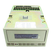
Exabyte EXB-8200 Installation Manual (34 pages)
Tabletop 8mm Cartridge Tape Subsystem
Brand:
Exabyte
| Category:
Tape Deck
| Size: 0 MB
Table of Contents
Table of Contents
7
Figure 1-1 Tabletop Cartridge Tape Subsystem
9
About this Manual
10
Related Publications
10
Other Test Standards
11
Regulatory and Safety Agency Standards
11
1 Introduction
9
About the Tabletop Cartridge Tape Subsystem
9
2 Installing the Tabletop CTS
12
Required Equipment and Tools
12
Requirements for Installing the Tabletop CTS
12
Unpacking the Tabletop CTS
13
Figure 2-1 Location of SCSI ID Switch and Connectors
14
Figure 2-2 Location of Power Switch and Power Connector
16
Figure 2-3 Location of Controls and Indicators (EXB-8200 Shown)
18
Failure to Power on
20
Performing the Initial Power-On
17
Setting the SCSI ID
14
Connecting Power to the Tabletop CTS
15
Connecting the Tabletop CTS to the SCSI Bus
15
3 Maintaining the Tabletop CTS
22
Cleaning the Cartridge Tape Subsystem
22
Serviceable Parts
23
Replacing the Fuse
23
Table 3-1 Serviceable Parts
23
Figure 3-1 Location of Fuse Drawer
24
Replacing the AC Power Cord
25
4 Packing and Shipping the Tabletop CTS
26
Packaging and Shipping Requirements
26
Preparing the Tabletop CTS for Shipping
26
Packing the Tabletop CTS
27
Appendix A Power Cord Requirements
28
And Canadian 220 VAC Power Cord
28
International 220 VAC Power Cord
29
Table B-1 SCSI Cable Specifications
30
Appendix B SCSI Cable Requirements
30
Index
34
Advertisement
Related Products
Exabyte EXB-8205
Exabyte EXB-8505 8mm
Exabyte EXB-8205XL
Exabyte EXB-8505XL
Exabyte EXB-8500c
Exabyte EXB-8700
Exabyte EXB-8500
Exabyte EXB-8200SX
Exabyte EZ17M
Exabyte EZ17A
Exabyte Categories
Storage
Test Equipment
Computer Hardware
Accessories
Robotics
More Exabyte Manuals
Login
Sign In
OR
Sign in with Facebook
Sign in with Google
Upload manual
Upload from disk
Upload from URL