Sign In
Upload
Manuals
Brands
evertz Manuals
Network Hardware
5700MSC-IP
evertz 5700MSC-IP Network Grand Clock Manuals
Manuals and User Guides for evertz 5700MSC-IP Network Grand Clock. We have
1
evertz 5700MSC-IP Network Grand Clock manual available for free PDF download: User Manual
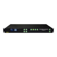
evertz 5700MSC-IP User Manual (100 pages)
IP Network Grand Master Clock & Video Master Clock System
Brand:
evertz
| Category:
Network Hardware
| Size: 2 MB
Table of Contents
Table of Contents
5
Overview
11
Figure 1-1: Front View of the 5700MSC-IP
11
Quick Start Guide
13
Mounting and Power Connections
13
Front Panel Installation
13
Configuring the Ethernet Ports
13
Figure 1-2: Ethernet Port Configuration
14
Selecting and Connecting the Frequency References
15
Selecting and Connecting Time References
16
Configuring PTP
16
Figure 1-3: PTP All Ports Menu
17
Figure 1-4: PTP Gige 1
17
Configuring PCR
18
Figure 1-5: PCR Gige 1 Menu
18
Checking the Status of the Unit
19
Wiring the Outputs
19
Configuring the Sync Outputs
19
Figure 1-6: 5700MSC-IP Rear Panel View
19
Configuring the Test Generator Outputs
20
Configuring the Time Outputs
20
Final Steps of Set up and Securing All Connections
21
Access Control
21
Technical Specifications
23
Analog Sync Outputs
23
Gps/Glonass Receiver
23
1000Base-T Network
23
10Gbe Timing Network
23
Genlock Input (Video/10Mhz Selectable)
23
Sdi Test Generators (with +Sdi-Tg, or +10G-Tg Options)
24
Physical
24
Electrical
24
Aux Expansion Module Option (Aes & Analog Audio Test Set, Dars, Gpio, and Ltc)
25
LTC Outputs
25
DARS & AES Test Generator Outputs
25
Analog Audio Tone Generator
25
General Purpose Inputs and Output
25
Theory of Operation
27
Outputs
27
Sync Outputs
27
Test Generator Options
30
Global Pedestal Control
30
Global Phase Controls
30
Figure 3-1: IRIG-B127 Format and Alignment to IRIG1 Datum Pulse
32
Figure 3-2: 29.97Hz LTC Format and Alignment to NTSC Video
32
Figure 3-3: PAL Alignment to 1Hz Pulse and PAL Color Frame Pulse
33
Figure 3-4: NTSC Alignment to 1/1.001Hz Pulse and 6/1.001Hz Pulse with VITC Color Framing
33
Genlock
34
Frequency Locking
34
Figure 3-5: Main Oscillator Circuit Block Diagram
34
Selecting the Frequency Reference Type
35
Selecting the Genlock Range
35
Lock Type Selection
36
Video Genlock Operation
38
Serial Digital Video Timing
38
NTSC Genlock Operation
39
Figure 3-6: Lock Diagram #1 - NTSC Reference Without 10Field Reference
39
NTSC Genlock with Ten-Field Reference
41
Figure 3-7: Lock Diagram #2 - NTSC Reference with Ten-Field Reference
41
Figure 3-8: SMPTE ST 318 Ten-Field Reference on NTSC Line 15
42
PAL Video Genlock Operation
43
Figure 3-9: Lock Diagram #3 - PAL Genlock
43
HD Tri-Level Genlock
45
Figure 3-10: Lock Diagram #4 - HD Tri-Level Genlock Operation
45
Slo-PAL Genlock
46
Continuous Wave and Internal References
47
Figure 3-11: Lock Diagram #5 - 10Mhz and Internal Frequency References
47
GNSS Frequency Reference
49
Figure 3-12: Lock Diagram #6 - GNSS Frequency Reference
49
Timekeeping
50
Time Lock Types
51
Figure 3-13: 5700MSC-IP Jam Modes
51
Coordinated Universal Time (UTC)
52
Time Reference Sources
52
Figure 3-14: 5700MSC-IP Time Reference Sources
53
LTC and VITC Timecode
55
Figure 3-15: Detail of 29.97Hz LTC Waveform Alignment to NTSC Video
55
Figure 3-16: Dropframe Timecode with Respect to Real-Time over a 1-Hour Period
57
Figure 3-17: Dropframe Timecode with Respect to Real-Time over a 24-Hour Period
57
Figure 3-18: Daily Time Jam Event for 29.97Hz Dropframe Timecode
58
Figure 3-19: Dropframe Timecode with Respect to Real-Time over One Week
59
IRIG Timecode
60
Figure 3-20: Detail of IRIG Alignment to IRIG Datum Pulse
60
Network Time Protocol (Ntp)
61
Figure 3-21: IRIG Input and Output Connections
61
Global Navigation Satellite System
62
Overview
62
Figure 3-22: Testing the NTP Server
62
GNSS Lock Operation
63
GNSS Re-Lock in Slow Mode
64
GNSS Position Insertion into Timecode
64
Automatic Changeover Operation
65
Installation
67
Rear Panel
67
Reference Loop Connections
67
Sync Outputs
67
Figure 4-1: 5700MSC-IP Rear Panel
67
Ethernet Connections
68
Serial Port Connection
69
GNSS Connection
69
AUX Connections (Available with 5700MSC-IP+AUX Option)
70
GPIO, LTC Input, Secondary LTC Outputs
70
Unbalanced Audio Connections AES 1, 2 and 3 (Available with 5700MSC-IP+AUX Option)
70
DARS out (Available with 5700MSC-IP+AUX Option)
71
Balanced Audio Connections (Available with 5700MSC-IP+AUX Option)
71
Test Generator Connections (SDTG, HDTG, 3GTG Options)
71
Power Connections
71
M4 Grounding Stud
72
Mounting and Cooling
72
Connecting the General Purpose Inputs and Outputs
72
Connecting Two 5700Msc-Ip Units in Syncro Mode
73
Gnss Receiver Installation
73
Mounting the GNSS Smart Antenna
73
Figure 4-2: Pole Mounting the Smart Antenna
74
Connecting the GNSS Smart Antenna to the 5700MSC-IP
75
System Start-Up
76
Operation
77
Front Panel Controls
77
Front Panel Buttons
77
Figure 5-1: Model 5700MSC-IP Front Panel Layout
77
The Status Screens
78
Panel Lock Function
81
Front Panel LCD Displays
81
Front Panel Menu System
82
Configuring the Input References
83
Configuring the Frequency Reference
84
Configuring the Time Inputs
86
Configuring the Jam Input
88
Configuring the Outputs
90
Configuring the Sync Outputs
91
Figure 5-2: Video Sync Phase Alignment in 59.94Hz Field Rate Systems
96
Figure 5-3: Video Sync Phase Alignment in 50Hz Field Rate Systems
96
General Configuration Items
98
Snmp Remote Control with Vistalink
98
Upgrading the Firmware
99
Uploading the Firmware
99
Uploading the Firmware Using FTP over Ethernet
99
Servicing Instructions and Troubleshooting
99
Changing the Fuses
99
Replacing the Battery
99
Advertisement
Advertisement
Related Products
evertz 5700ACO
evertz 5601AC02
evertz 5600ACO2
evertz 5600ACO
evertz 5010-GPSII
evertz 5010-GPSII-VITC
evertz 5950
evertz exponent 500ACO2-HD/SD
Evertz 5700MSC
evertz 2400ODU
evertz Categories
Media Converter
Network Hardware
Amplifier
Transmitter
Receiver
More evertz Manuals
Login
Sign In
OR
Sign in with Facebook
Sign in with Google
Upload manual
Upload from disk
Upload from URL