Sign In
Upload
Manuals
Brands
evertz Manuals
Clock
5601MSC
evertz 5601MSC Manuals
Manuals and User Guides for evertz 5601MSC. We have
2
evertz 5601MSC manuals available for free PDF download: Instruction Manual
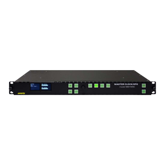
evertz 5601MSC Instruction Manual (196 pages)
Master SPG/Master Clock System
Brand:
evertz
| Category:
Clock
| Size: 6 MB
Table of Contents
Table of Contents
9
Overview
17
Figure 1-1: Front View of the 5601MSC
17
Quick Start Guide
19
Mounting and Power Connections
19
Front Panel Installation
19
Figure 1-2: 5601MSC with Front Panel Removed and Other Components Partially Extracted
19
Configuring the Ethernet Ports
20
Selecting and Connecting Frequency References
20
Selecting and Connecting Time References
21
Checking the Status of the Unit
22
Wiring the Outputs
22
Figure 1-3: Rear View of 5601MSC
22
Configuring the Sync Outputs
23
Configuring the Test Generator Outputs
23
FTP Feature
24
Configuring the Time Outputs
24
Figure 1-4: Front Panel Removed, Compactflash Location
24
Final Steps of Set up and Securing All Connections
25
Access Control
25
Theory of Operation
27
Figure 2-1: 5601MSC Outputs Block Diagram
27
Outputs
28
Sync Outputs
28
Timecode Outputs (LTC & IRIG)
30
Test Generator Options (SDTG, HDTG, 3GTG)
31
Global Pedestal Control
31
Global Phase Controls
31
Table 2-1: Global Phasing Characteristics
32
Figure 2-2: IRIG-B127 Format and Alignment to IRIG1 Datum Pulse
33
Figure 2-3: 29.97Hz LTC Format and Alignment to NTSC Video
33
Figure 2-4: PAL Alignment to 1Hz Pulse and PAL Color Frame Pulse
34
Figure 2-5: NTSC Alignment to 1/1.001Hz Pulse and 6/1.001Hz Pulse with VITC Color Framing
34
Genlock
35
Frequency Locking
35
Figure 2-6: Main Oscillator Circuit Block Diagram
35
Table 2-2: Frequency Reference Types for the 5601MSC
35
Selecting the Frequency Reference Type
36
Selecting the Genlock Range
36
Lock Type Selection
37
Table 2-3: Genlock Range Characteristics
37
Video Genlock Operation
39
Table 2-4: Supported Analog Video Sync References
39
Serial Digital Video Timing
40
NTSC Genlock Operation
41
Figure 2-7: Lock Diagram #1 - NTSC Reference Without 10Field Reference
41
NTSC Genlock with Ten-Field Reference
43
Figure 2-8: Lock Diagram #2 - NTSC Reference with Ten-Field Reference
43
Figure 2-9: SMPTE ST 318 Ten-Field Reference on NTSC Line 15
44
PAL Video Genlock Operation
45
Figure 2-10: Lock Diagram #3 - PAL Genlock
45
HD Tri-Level Genlock
47
Figure 2-11: Lock Diagram #4 - HD Tri-Level Genlock Operation
47
Slo-PAL Genlock
48
Table 2-5: Phase Locking to HD Tri-Level Standards
48
Table 2-6: Slo-PAL Phase Locking
48
Continuous Wave and Internal References
49
Figure 2-12: Lock Diagram #5 - 10Mhz and Internal Frequency References
49
Internal Frequency Reference
50
GPS Frequency Reference
51
Figure 2-13: Lock Diagram #6 - GPS Frequency Reference
51
Timekeeping
52
Figure 2-14: Time Locking Block Diagram
53
Time Lock Types
54
Coordinated Universal Time (UTC)
55
Time Reference Sources
55
GPS Time Reference
56
Modem Time Reference
56
Syncro Time Reference
57
LTC Time Reference
57
VITC Time Reference
57
IRIG Time Reference
58
SNTP Time Reference
58
No Time Reference
59
LTC and VITC Timecode
59
Figure 2-15: Detail of 29.97Hz LTC Waveform Alignment to NTSC Video
59
Dropframe Counting
60
Table 2-7: Supported LTC Frame Rates Summary
60
Figure 2-16: Dropframe Timecode with Respect to Real-Time over 1-Hour Period
61
Figure 2-17: Dropframe Timecode with Respect to Real-Time over a 24-Hour Period
61
LTC/VITC Timecode Color Framing
62
Figure 2-18: Daily Time Jam Event for 29.97Hz Dropframe Timecode
62
Figure 2-19: Dropframe Timecode with Respect to Real-Time over One Week
63
IRIG Timecode
64
Figure 2-20: Detail of IRIG Alignment to IRIG Datum Pulse
64
Table 2-8: Supported IRIG Timecode Formats
64
Figure 2-21: IRIG Input and Output Connections
65
Network Time Protocol (NTP)
66
Figure 2-22: Testing the NTP Server
66
Global Positioning System
67
Overview
67
GPS Lock Operation
67
Table 2-9: GPS Status Messages
68
GPS Re-Lock in Slow Mode
69
GPS Position Insertion into Timecode
69
Automatic Changeover Operation (5601ACO2)
70
Figure 2-23: Redundant Master Clock/Spg with Auto Changeover System Diagram
70
Installation
73
Rear Panel
73
Reference Loop Connections
73
Sync Outputs
73
Figure 3-1: 5601MSC Rear Panel
73
Ethernet Connections
74
Table 3-1: Standard 8-Pin Modular Connector Wiring Color Codes
74
Linear Time Code and IRIG Connections
75
Table 3-2: LTC out 1 and LTC out 2 XLR Pin Definitions
75
Serial Port Connection
76
GPS Connection
76
Table 3-3: COM Port Pin Definitions
76
Table 3-4: GPS Serial Port Pin Definitions
76
GPIO Connections (LTC Input, Secondary LTC Outputs, and Syncro Connections)
77
Unbalanced Audio Connections
77
Table 3-5: GPIO Pin Definitions
77
Balanced Audio and Modem Connections
78
Table 3-6: AUDIO Removable Terminal Block Pin Definitions
78
Test Generator Connections (SDTG, HDTG, 3GTG Options)
79
Serial Digital Video Test Generators
79
Analog Video Test Generators
79
Power Connections
79
M4 Grounding Stud
80
Mounting and Cooling
80
Connecting the General Purpose Inputs and Outputs
80
Figure 3-2: Typical GPI Circuitry
80
Figure 3-3: Typical GPO Circuitry
80
Connecting Two 5601Msc Units in Syncro Mode
81
Gps Receiver Installation (Gp Option)
81
Mounting the GPS Smart Antenna
81
Figure 3-4: Pole Mounting the Smart Antenna
82
Connecting the GPS Smart Antenna to the 5601MSC
83
Table 3-7: Evertz-Provided GPS Cable (Part WA-T09) Internal Wiring
83
System Start-Up
84
Table 3-8: Accutime Gold Extender Cable
84
How to Operate the Master Clock/Spg
85
Front Panel Controls
85
Front Panel Buttons
85
Figure 4-1: Model 5601MSC Front Panel Layout
85
The Status Screens
86
Figure 4-2 : Status Screen Highlighting to Indicate Warnings and Faults
87
Panel Lock Function
92
Front Panel LCD Displays
92
Figure 4-3: LCD Displays in Status Screen
92
Table 4-1: System Status Messages
92
Front Panel Menu System
93
Figure 4-4: Menu System and Selection List
93
Figure 4-5: Menu Item Live Control
93
Figure 4-6: Adjustment Live Control
94
Menu Reference Guide
95
Table 4-2: Input Menu System Tree
95
Table 4-3: Output Menu System Tree
101
Table 4-4: General Menu System Tree
105
Configuring the Input References
106
Selecting the Frequency Reference
106
Table 4-5: Root Level of the INPUT Menu
106
Configuring the Genlock Capture Range
107
Selecting the Frequency Reference Lock Type
107
Selecting the Time Reference
108
Setting the VITC Reader Line
109
Configuring the VITC and LTC Time Reference Date Format
109
Selecting the IRIG Input Mode
109
Selecting the SNTP IP Enable
110
Selecting the SNTP IP Address
110
Selecting the Time Reference Lock Type
111
Setting the Daily Jam Time for the Time Reference
111
Synchronizing the System Oscillator or System Time to the Reference Immediately
112
Configuring the Outputs
113
Table 4-6: Top Level of the Output Setup Menu
113
Configuring the LTC Outputs
114
Selecting Normal or Powered LTC 1 Output (LTC1 XLR Output Only)
114
Setting the LTC Output Frame Rate and IRIG
115
Selecting When the LTC Time Is Synchronized to the System Time
116
Synchronizing the LTC Output Time to System Time Immediately
116
Synchronizing All the LTC and VITC Outputs to System Time Immediately
116
Setting the LTC Frame Offset
116
Selecting the LTC Time Zone Offset
117
Enabling Daylight Saving Time for the LTC Output
117
Setting the LTC/IRIG Output Level
117
Enabling LTC Polarity Correction
118
Enabling the LTC Output Color Frame Bit
118
Selecting the IRIG Output Format
118
Setting a Time Offset to the IRIG Output
118
Configuring the Sync, 10MHZ and Wordclock Outputs
118
Selecting the Standard of the Sync Outputs
119
Configuring the VITC Generator for the Color Black Outputs
119
Setting the Phase of the Sync Outputs
125
Figure 4-7: Video Sync Phase Alignment in 59.94Hz Field Rate Systems
125
Figure 4-8: Video Sync Phase Alignment in 50Hz Field Rate Systems
125
Configuring the SDI Video Test Generator Outputs (SDTG, HDTG, 3GTG Options)
127
Selecting the SDI Test Generator Test Pattern
127
Selecting the Interface Type of the SDI Video Test Generator
127
Selecting the Image Format of the SDI Video Test Generator
128
Selecting Sampling Structure of the SDI Video Test Generator
128
Setting the Phase of the SDI Video Test Generator
129
Configuring the SDI Test Generator Embedded Audio
129
Configuring the On-Screen Message for the SDI Test Generator Outputs
131
Configuring the SDI Test Generator Output Drive
134
Setting the SDI Test Generator Syncro Mode
134
Configuring the Analog Video Test Generator Outputs (SDTG, HDTG, 3GTG Options)
134
Selecting the Test Pattern for the Analog Video Test Generator Output
134
Selecting the Standard of the Analog Video Test Generator
135
Setting the Phase of the Analog Video Test Generator
136
Configuring the On-Screen Message of the Analog Video Test Generator
137
Setting the Analog Test Generator Syncro Mode
140
Test Signals Available
141
Signal List for 525, and NTSC
141
Signal List for 625, and PAL
141
Signal List for HD, 1920X1080
141
Additional Test Signals in Compactflash for HD, 1920X1080
141
Signal List for HD, 1280X720
142
Additional Signals in Compactflash for HD, 1280X720
142
Signal List for 2048X1080, 3GB and Dual Link
142
Additional Signals in Compactflash for 2048X1080, 3GB and Dual Link
142
Configuring the Analog Audio Outputs
142
Setting the Analog Audio Tone Frequency
143
Configuring the Analog Audio Tone Level
143
Setting the Analog Audio Generation Mode
143
Configuring the Analog Audio Events
144
Configuring the AES and DARS Digital Audio Outputs
145
Setting the AES, DARS, and Wordclock Locking Mode
145
Setting the Phase of the AES and DARS Outputs
146
Setting the Phase of the Wordclock Outputs
146
Selecting the Tones to Generate on the AES Digital Audio Outputs
147
Setting the Audio Levels for the AES Digital Audio Outputs
147
Enabling the Setup Pedestal for All Sync and Analog Test Generator Outputs
147
Configuring Global Phase
148
Enabling or Disabling the Global Phase Offset
148
Entering a Global Phase Offset
148
General Configuration Items
149
Setting the System Time
149
Setting the System Date
149
Setting the Leap Seconds
149
Table 1-1: Top Level of the General Setup Menu
149
Setting the VITC/LTC Userbits
150
Setting the VITC/LTC Date Format
150
Enabling Syncro Mode
151
Setting the GPO 1 and 2 Mode
151
Initiating a Firmware Upgrade
152
Engineering Menu - Configuring SNMP and Front Panel Menu Access
152
Entering the Engineering Menu Password
152
Changing the Engineering Menu Password
153
Configuring the Simple Network Management Protocol (SNMP)
153
Configuring Access to Front Panel Menus
157
Setting the Number of Power Supplies Installed
159
Resetting the GPS Receiver
159
Setting the Daylight Saving Time Rules
159
Setting the DST Date Entry Mode
161
Setting the DST Start Hour
161
Setting the DST Start Day
161
Setting the DST Start Week
161
Setting the DST Start Month
162
Setting the End Hour
162
Setting the DST End Day
162
Setting the DST End Week
162
Setting the DST End Month
162
Setting the DST Offset
163
Saving and Recalling Presets
163
Recalling a User Defined Preset
163
Recalling a Factory Preset
163
Saving a User Defined Preset
164
Configuring the IP Settings for the CONTROL and TIME Ethernet Ports
164
Setting up the IP Address for the CONTROL Ethernet Port
164
Setting up the Internet Protocol Subnet Mask for the CONTROL Ethernet Port
164
Setting up the IP Address for the TIME Ethernet Port
164
Setting up the Internet Protocol Subnet Mask for the TIME Ethernet Port
165
Setting up the Internet Protocol Gateway Address
165
Enabling or Disabling Usage of the Internet Protocol Gateway
165
Configuring IP Broadcast Packet Handling
165
Configuring the Network Time Protocol Functions (Units Fitted with the T Option)
166
Enabling NTP Spoofing
166
Configuring the NTP Restrictions
167
Configuring the Precision Time Protocol Master
168
Master en
168
Master Mode
168
Setting the PTP DSCP Value
169
Setting the Sync Rate
169
Setting the Announce Rate
169
Setting the Timeout Value
169
PTP Priority 1
169
PTP Priority 2
170
Setting the PTP Domain
170
GMP Enable
170
Ptp
170
Accuracy
171
Parts
171
Configuring PTP
171
Snmp Remote Control with Vistalink
173
Updating Vistalink® with a New JAR File
173
Figure 4-9: Selecting the Version Information Menu Item
174
Figure 4-10: Version Information Dialog
174
Applying a JAR Update to the Vistalink® Pro Server
175
Figure 4-11: Updating the Vistalink
175
Figure 4-12 : Server Restart Warning
175
Applying a JAR Update to the Client-Only Version of Vistalink® Pro
176
Vistalink® Pro Control Screens for the 5601MSC
176
Figure 4-13: Client Notification of JAR Update from Server
176
Alarm View Screen
177
Figure 4-14: Vistalink Right-Click Pop-Up Menu
177
Figure 4-15: Vistalink® Pro Alarm View
178
Control View Screens
179
Figure 4-16: Vistalink Tabbed Control View
179
Table 4-8: Vistalink
180
Technical Description
181
Specifications
181
Analog Sync Outputs
181
LTC/IRIG Outputs
181
Communications and Control
181
Serial Port
181
Modem: (M Option Installed)
182
Ethernet
182
GPS Receiver (GP Option Installed)
182
DARS & AES Test Generator Outputs (SDTG, HDTG, or 3GTG Options)
183
Reference Loop and Genlock
183
Analog Composite Video Test Signal Generators (SDTG, HDTG, or 3GTG Options)
184
Analog Audio Tones Generator (SDTG, HDTG, or 3GTG Options)
184
SDI Test Generator Outputs (SDTG, HDTG, or 3GTG Options)
184
HDTV Test Generator Outputs (HDTG Option Installed)
185
3GTV Test Generator Outputs (3GTG Option Installed)
186
General Purpose Inputs and Outputs
186
Power Supplies
187
Compliance
187
Mechanical and Environmental
187
Ordering Options
187
Upgrading the Firmware
188
Overview and Setup
188
Putting the 5601MSC into Upgrade Mode
188
Uploading the Firmware
189
Uploading the Firmware Using FTP over Ethernet
189
Servicing Instructions and Troubleshooting
190
Changing the Fuses
190
Replacing the Battery
190
Safety Guidelines and Precautions Concerning the Use of 3V Lithium Batteries
191
Procedure for Replacing the Battery
191
Troubleshooting Issues
192
Intermittent Errors on Devices Connected to the SDI Test Generator Outputs (SD/HD/3G)
192
GPS Related Issues
192
Front Panel Issues
193
Vistalink® Pro Issues - SNMP Problems
194
Unit Is Not Locking to the Frequency Reference
196
Figure 5-1 : Example of the Vistalink(R) Pro Server Sucessfully Binding Port 162
196
Advertisement
evertz 5601MSC Instruction Manual (128 pages)
Master SPG/Master Clock System
Brand:
evertz
| Category:
Network Hardware
| Size: 2.37 MB
Table of Contents
Table of Contents
7
Overview
15
Figure 1-1: Front View of the 5601MSC
15
Figure 1-2: Redundant Master Clock/Spg with Auto Changeover System Diagram
17
Quick Start Guide
18
Mounting and Power Connections
18
Front Panel Installation
18
Figure 1-3: 5601MSC with Front Panel Removed and Other Components Partially Extracted
18
Configuring the Ethernet Ports
19
Selecting and Connecting Frequency References
19
Selecting and Connecting Time References
20
Checking the Status of the Unit
21
Wiring the Outputs
21
Figure 1-4: Rear View of 5601MSC
21
Configuring the Sync Outputs
22
Configuring the Test Generator Outputs
22
Configuring the Time Outputs
23
Final Steps of Set up and Securing All Connections
23
Access Control
23
Installation
27
Rear Panel
27
Reference Loop Connections
27
Sync Outputs
27
Ethernet Connections
28
Table 2-1: Standard 8-Pin Modular Connector Wiring Color Codes
28
Linear Time Code Connections
29
Serial Port and Modem Connections
29
Table 2-2: LTC out 1 and LTC out 2 XLR Pin Definitions
29
Table 2-3: COM Port Pin Definitions
29
LTC Input, Secondary LTC Outputs, and Syncro Connections
30
Table 2-4: GPS Serial Port Pin Definitions
30
Table 2-5: GPIO Pin Definitions
30
Analog Audio and Modem Connections
31
Table 2-6: AUDIO Terminal Strip Pin Definitions
31
Test Generator Connections (SDTG, HDTG, 3GTG Options)
32
Power Connections
32
M4 Grounding Stud
32
Mounting and Cooling
33
Connecting the General Purpose Inputs and Outputs
33
Connecting Two 5601Msc Units in Syncro Mode
34
Gps Receiver Installation (Gp Option)
34
Mounting the GPS Smart Antenna
34
Connecting the GPS Smart Antenna to the 5601MSC
36
System Start-Up
37
How to Operate the Master Clock/Spg
43
Front Panel Controls
43
Front Panel Buttons
43
The Status Button
44
Panel Lock Function
46
Front Panel LCD Displays
46
Table 3-1: System Status Messages
47
Front Panel Menu System
48
Menu Reference Guide
50
Table 3-2: Menu System
57
Configuring the Input References
58
Selecting the Frequency Reference
58
Table 3-3: Root Level of the INPUT Menu
58
Configuring the Genlock Capture Range
62
Selecting the Frequency Reference Lock Type
62
Wide and Narrow Genlock Ranges
63
Selecting the Time Reference
64
Setting the VITC Reader Line
64
Configuring the VITC and LTC Time Reference Date Format
65
Selecting the Time Reference Lock Type
65
Synchronizing the System Oscillator or System Time to the Reference Immediately
66
Configuring the Outputs
67
Configuring the LTC Outputs
67
Table 3-4: Top Level of the Output Setup Menu
67
Selecting Normal or Powered LTC 1 Output (LTC1 XLR Output Only)
68
Setting the LTC Output Frame Rate
69
Selecting When the LTC Time Is Synchronized to the System Time
70
Synchronizing the LTC Output Time to System Time Immediately
70
Synchronizing All the LTC and VITC Outputs to System Time Immediately
70
Setting the LTC Frame Offset
71
Selecting the LTC Time Zone Offset
71
Enabling Daylight Saving Time for the LTC Output
71
Setting the LTC Output Level
71
Enabling LTC Polarity Correction
72
Enabling the LTC Output Color Frame Bit
72
Configuring the Sync, 10MHZ and Wordclock Outputs
73
Selecting the Standard of the Sync Outputs
73
Configuring the VITC Generator for the Color Black Outputs
74
Enabling VITC on the Video Output
74
Selecting the VITC Insertion Lines
74
Enabling Drop Frame Counting for NTSC VITC
74
Selecting When the VITC Time Is Synchronized to the System Time
75
Synchronizing the VITC to System Time Immediately
75
Synchronizing All the VITC and LTC Outputs to System Time Immediately
76
Setting the VITC Frame Offset
76
Selecting the VITC Time Zone Offset
76
Enabling Daylight Saving Time for the VITC on the Sync Output
77
Enabling Insertion of the Ten Field Reference
77
Selecting the Pulse Type
77
Selecting the Sine Wave Level
78
Selecting the Wordclock Level
78
Setting the Phase of the Sync Outputs
79
Configuring the SDI Video Test Generator Outputs (SDTG, HDTG, 3GTG Options)
81
Selecting the SDI Test Generator Test Pattern
81
Selecting the Standard of the SDI Video Test Generator Link Format
81
Selecting the Standard of the SDI Video Test Generator Image Format
82
Setting the Phase of the SDI Video Test Generator
82
Configuring the SDI Test Generator Embedded Audio
83
Controlling Embedding of Audio Groups Onto the SDI Test Generator
83
Selecting the Audio Tone for an SDI Embedded Audio Channel
83
Setting the Audio Level for an SDI Embedded Audio Channel
84
Configuring the On-Screen Message for the SDI Test Generator Outputs
84
Enabling the On-Screen Message for the SDI Test Generator
84
Setting the On-Screen Message Position for the SDI Test Generator
84
Entering User-Defined Text for the On-Screen Message
85
Selecting the Font Size of the On-Screen Message for the SDI TG
85
Configuring the SDI Test Generator Output Drive
85
Setting the SDI Test Generator Syncro Mode
86
Configuring the Analog Video Test Generator Outputs (SDTG, HDTG, 3GTG Options)
86
Selecting the Test Pattern for the Analog Video Test Generator Output
86
Selecting the Standard of the Analog Video Test Generator
86
Setting the Phase of the Analog Video Test Generator
87
Configuring the On-Screen Message for Analog Video Test Generator 1
88
Enabling the On-Screen Message for Analog Video Test Generator 1
88
Setting the On-Screen Message Position for ATG 1
88
Entering User-Defined Text for the On-Screen Message of ATG 1
88
Setting the Font Size for the On-Screen Message of ATG 1
89
Setting the Analog Test Generator Syncro Mode
89
Configuring the Analog Audio Outputs
90
Setting the Analog Audio Tone Frequency
90
Configuring the Analog Audio Tone Level
90
Configuring the AES and DARS Digital Audio Outputs
91
Setting the AES, DARS, and Wordclock Locking Mode
91
Setting the Phase of the AES and DARS Outputs
91
Setting the Phase of the Wordclock Outputs
91
Selecting the Tones to Generate on the AES Digital Audio Outputs
92
Setting the Audio Levels for the AES Digital Audio Outputs
92
Enabling the Setup Pedestal for All Sync and Analog Test Generator Outputs
92
Configuring Global Phase
92
Enabling or Disabling the Global Phase Offset
93
Entering a Global Phase Offset
93
General Configuration Items
94
Setting the System Time
94
Setting the System Date
94
Table 3-5: Top Level of the General Setup Menu
94
Setting the VITC/LTC Userbits
95
Setting the VITC/LTC Date Format
95
Enabling Syncro Mode
96
Configuring the Modem (Units Fitted with the M Option)
97
Setting the Modem Operating Mode
97
Setting the Modem Standard
97
Setting the Modem Speaker Volume
98
Setting the Modem Phone Number to Dial
98
Setting the Auto Dial Time
98
Setting the Auto Dial Day
99
Dialling the Modem Immediately
99
Cancelling the Current Call
99
Setting the Number of Times the Modem will Retry a Failed Call
99
Setting the GPO 1 and 2 Mode
100
Initiating a Firmware Upgrade
100
Engineering Menu - Configuring SNMP and Front Panel Menu Access
101
Entering the Engineering Menu Password
101
Changing the Engineering Menu Password
101
Configuring the Simple Network Management Protocol (SNMP)
101
Enabling and Disabling SNMP
102
Changing the SNMP Read and Write Community Strings
102
Configuring the SNMP Trap Destinations
103
Enabling and Disabling SNMP Traps
104
Configuring Access to Front Panel Menus
105
Enabling and Disabling Front Panel Menu Access Control
105
Setting the Front Panel Menu Restrictions
106
Setting the Number of Power Supplies Installed
107
Setting the Daylight Saving Time Rules
107
Setting the DST Date Entry Mode
108
Setting the DST Start Hour
109
Setting the DST Start Day
109
Setting the DST Start Week
109
Setting the DST Start Month
109
Setting the End Hour
109
Setting the DST End Day
110
Setting the DST End Week
110
Setting the DST End Month
110
Setting the DST Offset
110
Saving and Recalling Presets
111
Recalling a User Defined Preset
111
Recalling a Factory Preset
111
Saving a User Defined Preset
112
Configuring the IP Settings for the CONTROL Ethernet Port
112
Setting up the Internet Protocol Address Mode
112
Setting up the Internet Protocol Address
112
Setting up the Internet Protocol Subnet Mask
112
Setting up the Internet Protocol Gateway Address
113
Enabling or Disabling Usage of the Internet Protocol Gateway
113
Configuring the Network Time Protocol Functions (Units Fitted with the T Option)
113
Enabling NTP Spoofing
114
Configuring the NTP Restrictions
114
Setting the NTP Restriction Mode
115
Setting the NTP Restriction IP Address
115
Setting the NTP Restriction Mask
115
OPERATING with GLOBAL POSITIONING SYSTEM LOCK (GP Option)
116
The Global Positioning System Overview
116
GPS Lock Operation
116
GPS Position Insertion
116
Technical Description
119
Specifications
119
Analog Sync Outputs
119
LTC Outputs
119
Communications and Control
120
GPS Receiver (GP Option Installed)
120
DARS & AES Test Generator Outputs (SDTG, HDTG, or 3GTG Options)
121
Reference Loop and Genlock
121
Analog Composite Video Test Signal Generators (SDTG, HDTG, or 3GTG Options)
122
Analog Audio Tones Generator (SDTG, HDTG, or 3GTG Options)
122
SDI Test Generator Outputs (SDTG, HDTG, or 3GTG Options)
122
HDTV Test Generator Outputs (HDTG Option Installed)
123
3GTV Test Generator Outputs (3GTG Option Installed)
123
General Purpose Inputs and Outputs
123
Power Supplies
124
Mechanical and Environmental
124
Ordering Options
124
Upgrading the Firmware
125
Overview and Setup
125
Putting the 5601MSC into Upgrade Mode
125
Uploading the Firmware
126
Servicing Instructions
127
Changing the Fuses
127
Replacing the Battery
127
Safety Guidelines and Precautions Concerning the Use of 3V Lithium Batteries
128
Procedure for Replacing the Battery
128
Advertisement
Related Products
Evertz 5700MSC
evertz 5600MSC Series
evertz 5601AC02
evertz 5600ACO2
evertz 5600ACO
evertz 5010
evertz 5010-VITC-24
evertz 570J2K-HW-X19
evertz exponent 500IDA9-IG Series
evertz exponent 500ADA-EQ-L
evertz Categories
Media Converter
Network Hardware
Amplifier
Transmitter
Receiver
More evertz Manuals
Login
Sign In
OR
Sign in with Facebook
Sign in with Google
Upload manual
Upload from disk
Upload from URL