Sign In
Upload
Manuals
Brands
ETAS Manuals
Control Unit
ES511.1
User Manuals: ETAS ES511.1 CAN Module
Manuals and User Guides for ETAS ES511.1 CAN Module. We have
1
ETAS ES511.1 CAN Module manual available for free PDF download: User Manual
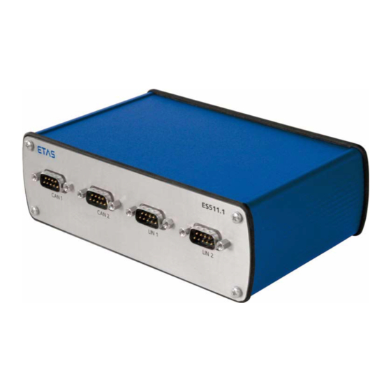
ETAS ES511.1 User Manual (69 pages)
CAN and LIN Network Module
Brand:
ETAS
| Category:
Control Unit
| Size: 2 MB
Table of Contents
Table of Contents
3
1 General Information
7
Basic Safety Instructions
7
Product Liability Disclaimer (ETAS Disclaimer)
7
Correct Use
9
Labeling of Safety Instructions
9
Demands Made Re the Technical State of the Product
9
Taking the Product Back and Recycling
10
Fig. 1-1 WEEE Symbol
10
About this Manual
11
Structure
11
Using this Manual
12
Package Contents
13
2 Hardware Description
15
Modules of the Es51X Line
15
ES511.1 Features
15
Fig. 2-1 ES511.1 View of the Device
15
Housing
17
Serial Number
17
Ports
17
Front Panel
17
Fig. 2-2 Ports and Leds
17
Back Panel
18
Leds
18
Overview
18
Fig. 2-3 Ports
18
LED Display
19
3 Functional Description
21
Block Diagram
21
Power Supply (6-32V DC)
21
Ethernet Switch
21
Fig. 3-1 Block Diagram
21
HOST" Port
22
ETH1", "ETH2", "ETH3" Port
22
Power-Saving Feature
23
CAN Interface ("CAN 1", "CAN 2")
23
Operating Modes
23
Feature
24
Bus Terminating Resistor
24
LIN Interface ("LIN 1", "LIN 2")
24
Operating Modes
24
Power Supply on the Bus
24
Flexray Interface ("FLEXRAY A", "FLEXRAY B")
25
Feature
25
Bus Termination Resistor
25
Fig. 3-2 Power Supply at the LIN Bus
25
Module Network
26
Time Synchronization
26
Firmware Update
27
4 Getting Started
29
Applications
29
ES511.1 with XETK, ES590 and ES400 Modules
29
Fig. 4-1 ES511.1 with XETK, ES590 and ES400 Modules
29
ES510.1 with ES511 and ES512 Measure Modules
30
Fig. 4-2 ES510.1 with ES511 and ES512 Measure Modules
30
Wiring
31
HOST" Port
31
6-32V" Port
31
ETH1", "ETH2", "ETH3" Port
32
Fig. 4-3 Example of a Module Network
33
Configuring the ES511.1
34
Web Interface
34
Launching the ES511.1 Web Interface
34
Configuring the "Auto / on Switch" Function
34
5 Technical Data
37
General Data
37
Fulfilled Standards and Norms
37
Environmental Conditions
37
Mechanical Data
38
System Requirements
38
Hardware
38
Ethernet Interface of the PC
38
Supported Applications and Software Requirements
38
Electrical Data
39
Interface „HOST
39
Power Supply
40
Ethernet Interfaces
40
CAN Interfaces ("CAN 1" and "CAN 2")
41
LIN Interfaces ("LIN 1" and "LIN 2")
41
Pin Assignment
42
Interface „6-32V
42
Fig. 5-1 Interface „6-32V
42
Interface „HOST
43
Interface „ETH1
43
Interface „ETH2
44
Interface „ETH3
44
Interface „CAN 1
45
Interface „CAN 2
45
Interface „LIN 1
46
Interface „LIN 2
46
6 Cable and Accessories
47
Power Supply Cable
47
Fig. 6-1 CBP510-2 Cable
47
Ethernet Cable
48
CBE500-3 Cable
48
CBE530-X Cable
48
Fig. 6-2 CBE500-3 Cable
48
Fig. 6-3 CBE530-X Cable
48
CAN-/ LIN-/ Flexray Cable
49
CAN Terminating Resistor
49
Fig. 6-4 CBH500-2 Cable
49
Fig. 6-5 CBCX131-0 Terminating Resistor
49
7 Ordering Informationen
51
Accessoires
51
Power Supply Cables
51
Ethernet Cables
51
CAN-/ LIN-/ Flexray Cable
51
CAN Termination Resistor
52
8 Appendix: Troubleshooting Problems
53
Error Leds
53
Troubleshooting ES511.1 Problems
53
Problems and Solutions
54
Network Adapter Cannot be Selected Via Network Manager
54
Search for Ethernet Hardware Fails
55
Personal Firewall Blocks Communication
57
9 ETAS Contact Addresses
63
List of Figures
65
Index
67
Advertisement
Advertisement
Related Products
ETAS ES585.1
ETAS ES584.1
ETAS ES581.4
ETAS ES5385.1
ETAS ES582.1
ETAS ES592.1
ETAS ES523.1
ETAS ES582.2
ETAS ES430.1
ETAS ES4457.1
ETAS Categories
Control Unit
Computer Hardware
Measuring Instruments
Recording Equipment
I/O Systems
More ETAS Manuals
Login
Sign In
OR
Sign in with Facebook
Sign in with Google
Upload manual
Upload from disk
Upload from URL