Sign In
Upload
Manuals
Brands
ESD Manuals
Control Unit
C.3032.02
ESD C.3032.02 Manuals
Manuals and User Guides for ESD C.3032.02. We have
1
ESD C.3032.02 manual available for free PDF download: Manual
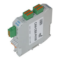
ESD C.3032.02 Manual (120 pages)
4x RTD (PT100, PT1000)
Brand:
ESD
| Category:
Control Unit
| Size: 4 MB
Table of Contents
Table of Contents
5
Overview
7
Description of the Module
7
Quick Start
9
Technical Data
10
General Technical Data
10
Microcontroller
11
CAN Interface
11
Sensor Resistor Inputs
12
Software Support
12
Connecting Diagram
13
Power Supply and CAN
13
Connect Temperature Sensor in 2-Wire Configuration (Example Pt2)
14
Connect Temperature Sensor in 4-Wire Configuration (Example Pt2)
15
LED Display
16
Indicator States
16
Operation of the CAN-Error LED
17
Operation of the Canopen-Status LED
17
Operation of the Error-LED
18
Operation of the Power-LED
18
Special Indicator States
19
Assignment of the LED Labelling to the Name in the Schematic Diagram
19
Coding Switches
20
Setting the Node-ID Via Coding Switch
20
Setting the Baud Rate
21
Assignment of Coding-Switch Labelling to Name in Schematic Diagram
21
Connecting Power Supply and CAN-Signals to CBX-Inrailbus
23
Connection of the Power Supply Voltage
24
Connection of CAN
25
Remove the CAN-CBX Module from the Inrailbus
25
Connector Assignment
26
Power Supply Voltage 24 V (X100)
26
Can
27
CAN Interface
27
CAN Connector
28
CAN and Power Supply Voltage Via Inrailbus Connector
29
Temperature Sensor Interface Pt1
30
Assignment of Module Labelling to Name in Schematic Diagram
31
Conductor Connection/Conductor Cross Sections
32
Correct Wiring of Electrically Isolated CAN Networks
33
Standards Concerning CAN Wiring
33
Light Industrial Environment (Single Twisted Pair Cable)
34
General Rules
34
Cabling
35
Termination
35
Heavy Industrial Environment (Double Twisted Pair Cable)
36
General Rules
36
Device Cabling
37
Termination
37
Electrical Grounding
38
Bus Length
38
Examples for CAN Cables
39
Cable for Light Industrial Environment Applications (Two-Wire)
39
Cable for Heavy Industrial Environment Applications (Four-Wire)
39
CAN Troubleshooting Guide
40
Termination
40
Electrical Grounding
41
Short Circuit in CAN Wiring
41
CAN_H/CAN_L Voltage
41
CAN Transceiver Resistance Test
42
Support by Esd
42
Canopen Firmware
43
Definition of Terms
43
NMT-Boot-Up
44
The Canopen-Object Directory
44
Communication Parameters of the Pdos
45
Access on the Object Directory
45
Overview of Used Canopen-Identifiers
48
Setting the COB-ID
48
Default PDO-Assignment
49
Reading the Analog Values
50
Messages of the Analog Inputs
50
Supported Transmission Types Based on DS-301
50
Communication Profile Area
51
Used Names and Abbreviations
51
Implemented Canopen-Objects
52
Overview of Used 1000-Objects and Default Values
52
Device Type (1000 )
54
Error Register (1001 )
55
Pre-Defined Error Field (1003 )
56
COB-ID of SYNC-Message (1005 )
58
Communication Cycle Period (1006 )
59
Manufacturer Device Name (1008 )
60
Manufacturer Hardware Version (1009 )
61
Manufacturer Software Version
61
Guard Time (100C ) und Life Time Factor
62
Node Guarding Identifier
63
Store Parameters (1010 )
64
Restore Default Parameters (1011 )
66
COB_ID Emergency Message (1014 )
68
Inhibit Time EMCY (1015 )
69
Consumer Heartbeat Time (1016 )
70
Producer Heartbeat Time (1017 )
72
Identity Object (1018 )
73
Synchronous Counter Overflow Value (1019 )
75
Verify Configuration (1020 )
76
Error Behaviour Object (1029 )
77
NMT Startup
78
Self Starting Nodes Timing Parameters (1F91 )
79
Object Transmit PDO Communication Parameter 1800
80
Transmit PDO Mapping Parameter 1A00
81
Device Profile Area
82
Overview of the Implemented Objects 6110
82
Relationship between the Implemented Analog Input Objects
83
AI Sensor Type (6110 )
84
AI Operating Mode (6112 )
86
AI ADC Sampling Rate (6114 )
87
AI Physical Unit (6131 )
88
AI Decimal Digits PV (6132 )
90
AI Status (6150 )
91
Analog Input Field Value (9100 )
92
AI Interrupt Delta Input FV (9103 )
93
Analog Input Process Value (9130 )
94
AI Interrupt Delta Input PV (9133 )
95
AI Interrupt Lower Limit PV (9134 )
96
AI Interrupt Upper Limit PV (9135 )
97
Manufacturer Specific Profile Area
98
Adc_Pga (2400 )
99
Channel Enabled (2401 )
100
Accu N (2402 )
101
Average N (2403 )
102
Current Source Value (2410 )
103
Local Temperature at PCB (2420 )
104
Local Temperature at the Last Calibration (2421 )
105
Calibration Delta Temperature (2422 )
106
Calibration Data
107
Calibration and Process/Field-Value Calculation
107
Reference Temperature at Calibration (2500 )
110
Gain Correction at I 8.11.10.4 Gain Correction PGA=2/3/4 (2503 )
112
Offset (2510 )
113
Firmware Management Via DS 302-Objects
115
Download Control Via Object 1F51
116
Verify Application Software
116
References
117
Glossary
117
EU-Declaration of Conformity
118
Order Information
119
Advertisement
Advertisement
Related Products
ESD C.3010.02
ESD C.2066.21
ESD CAN-USB/2
ESD CAN-CBX-Pt100
ESD CAN-CBX-AO412
ESD CAN-USB/3-FD
ESD CAN-CBM-REL4
ESD CAN-CBM-AI410
ESD CAN-CBX-DIO8
ESD CAN-CBX-DIO8-J1939
ESD Categories
Recording Equipment
Computer Hardware
Gateway
PCI Card
Control Unit
More ESD Manuals
Login
Sign In
OR
Sign in with Facebook
Sign in with Google
Upload manual
Upload from disk
Upload from URL