Sign In
Upload
Manuals
Brands
Entron Manuals
Controller
EN1001 series
Entron EN1001 series Manuals
Manuals and User Guides for Entron EN1001 series. We have
2
Entron EN1001 series manuals available for free PDF download: Instructions Manual, Installation And Operation Manual
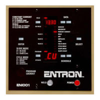
Entron EN1001 series Instructions Manual (167 pages)
MICROPROCESSOR BASED Weld Sequence Controls With Solid State Thyristor Contactors
Brand:
Entron
| Category:
Controller
| Size: 4 MB
Table of Contents
Table of Contents
4
1 General Description
9
Figure 1-1 En1000/En1001 System
9
Standard Features
10
Control Panel Layout
11
Figure 1-2 Control Panel Layout
11
2 Programmable Functions
12
Control Functions
12
Sequence Timed Parameters
14
Other Programmable Sequence Parameters
15
Table 2-1 Slope Modes
15
Table 2-2 Cycle Modes
15
Table 2-3 Valve Codes
16
3 Installation
17
Installation and Mounting Diagrams - "S" Cabinet
17
Figure 3-1 Installation and Mounting Diagrams for Style "S" Cabinet
17
Installation and Mounting Diagrams - "E" Cabinet
18
Figure 3-2 Installation of Style "E" Cabinet - 300A & 1200A Contactor
18
Figure 3-3 Installation of Style "E" Cabinet - 1800/2200/3200A Contactor
18
Figure 3-4 Mechanical Mounting Diagram for "E" Cabinet
18
Installation and Mounting Diagrams - "T/D" and "L" Cabinet
19
Figure 3-5 Installation of Style "T/D" & "L" Cabinets - 1200A Contactor
19
Figure 3-6 Installation of Style "T/D" & "L" Cabinets - 1800/2200/3200A Contactor
19
Figure 3-7 Mechanical Mounting Diagram for "T/D" and "L" Cabinets
19
Installation and Mounting Diagrams - "C" Cabinet
20
Figure 3-8 Installation Diagram for Style "C" Cabinet
20
Figure 3-9 Mounting Diagrams for Style "C" Cabinet
20
Installation and Mounting Diagrams - Flat Plate and Imu
21
FIGURE 3-10 INSTALLATION and MOUNTING DIAGRAMS for 11X11 FLAT PLATE
21
FIGURE 3-11 INSTALLATION and MOUNTING DIAGRAMS for 21X21 FLAT PLATE
21
FIGURE 3-12 INSTALLATION and MOUNTING DIAGRAMS for 13X19 FLAT PLATE
22
Figure 3-13 Installation and Mounting Diagrams for Imu
22
Welding Transformer Primary Wiring
23
External Scr Contactor Wiring
23
Table 3-1 External Scr Contactor Connections
23
Figure 3-14 External Scr Contactor Connections
24
Contactor Specifications
25
Figure 3-15 Demand Current Vs. Percent Duty Cycle
26
Cooling Requirements for Contactors
27
4 General Operating Requirements
28
Operating Voltage
28
Figure 4-1 Voltage Operation Jumpers Settings
28
Figure 4-2 Valve Transformer Jumpers Settings
29
Fusing and Safe Operation
30
Figure 4-3 Warning, Danger and Caution Labels
30
Terminal Strip Diagrams and Connections
31
Terminal Strip Ts1/Pcb2
31
Figure 4-4 Terminal Strip/Firing Board
31
Figure 4-5 Component Placement on New Terminal Strip/Firing Board
32
Terminal Strip Connections
33
Terminal Strip Ts1 Inside the Cabinet
35
Figure 4-6 Terminal Strip for "T/D" Cabinet
35
Initiation
36
Single Stage Pilot Initiation
36
Two Stage Pilot Initiation
36
Other Terminal Strip Inputs
36
Figure 4-7 Initiation Inputs on Terminal Strip Ts1
36
Figure 4-8 Other Inputs on Terminal Strip Ts1
37
Non-Volatile Memory Error
38
Figure 4-10 Wrong Routing of Low and High Voltage Wires
39
Figure 4-11 Better Routing of Low and High Voltage Wires
39
Figure 4-12 Recommended Routing of Low and High Voltage Wires
39
Isolation Circuitry Description
40
Figure 4-13 Isolation Circuit Block Diagram
40
5 Introduction to Data Programming
42
General Programming
42
Figure 5-1 Four-Digit Data Display
42
Program Lockout Options
43
Program Lockout Key Switch Option
43
Using Program Lockout Key Switch for Error Clearing
43
Sequence (Schedule) Parameters Programming
44
Using Programming Shortcuts
45
Figure 5-2 Copy Schedule up by 1
45
Figure 5-3 Copy Schedule up by 10
45
Figure 5-4 Clear Schedule Data
45
Extended Functions
46
Figure 5-5 Selecting Functions
46
Figure 5-6 Extended Functions Mode
46
Figure 5-7 Viewing Extended Functions
46
Identification Number
47
Seam Welding Mode
47
Schedule Select
50
Table 5-1 External Schedule Select with Fs7 and Fs11
51
Figure 5-8 Dual Two-Stage Foot Switch Initiation
52
Figure 5-9 Multiple Two-Stage Foot Switch Initiation
52
Figure 5-12 Switch Closure Connections
54
Table 5-2 S49 External Schedule Select
54
Figure 5-13 Multiple Pilot Switch Connections
55
Table 5-3 Stepper Selection Using Ss1, Ss2, Ss4, Ss8
55
Automatic Voltage Compensation and Monitoring
57
Table 5-4 Original Avc Values
57
Table 5-5 Avc Parameter Values
57
Clear All Functions
59
Figure 5-14 Clear Schedule Data
59
Back-Step / Temperature Limit Switch
60
Figure 5-15 Back-Step Sequence Example
60
Process Outputs
61
Table 5-6 Process Output Codes and Descriptions
62
Beat Operation Initiation Modes
66
Figure 5-16 Using Light Curtain
67
87° Delay
68
Manual Power Factor Programming
69
Power Factor Measuring
69
Blocking Delay
70
Squeeze Delay
70
Turns Ratio
70
Constant Current Modes
71
Table 5-7 Constant Current Modes
71
Range
72
Current Offset
73
Pin Lockout Mode
76
6 General Operating Instructions
77
Weld Sequence Example
77
Cycle Modes
78
Non-Repeat
78
Figure 6-1 Non-Repeat Sequence
78
Repeat
79
Chained
79
Figure 6-2 Repeat Sequence
79
Figure 6-3 Chained Sequence
80
Successive
81
Conditional Successive
82
Wait-Here
83
Table 6-1 Valve Codes
83
Slope Modes
84
No Slope
85
Upslope
85
Downslope
85
Valve Modes
86
Table 6-2 Valve Modes and Valve Outputs
86
7 Stepper on En1000/En1001 Series Controls
87
Figure 7-1 Stepper Enabling
87
Schedule Map
88
Table 7-1 Schedule Map Used for Stepper Programming
88
Stepper Programming
89
Extended Function Programming
89
Weld Sequence Programming
89
Step Counts Programming
89
Figure 7-2 Select Weld/Heat
89
Figure 7-3 Program Weld Count
89
Table 7-2 Stepper Codes
89
Last Step and Last Count Programming
90
Figure 7-4 Program Last Step
90
Figure 7-5 Program Last Count
90
Quick Setup Instructions for Stepper
91
Sequence (Schedule) Initiation in Stepper Mode
92
SCHEDULE SELECT OPTIONS for STEPPER MODE S.t
92
Table 7-3 Stepper Selection Using Fs7 and Fs11
92
Table 7-4 Stepper Selection Using Ss1, Ss2, Ss4, Ss8
92
Stepper Operation
93
OPERATION ALGORITHM for STEPPER MODE S.t
93
S.t
93
Figure 7-6 Algorithm
93
STEPPER OPERATION for STEPPER MODE S.t. S.t.=02 02 02 02 02
94
Table 7-5 Programming for Stepper Mode 02 02 02 02 02
94
Stepper Reset
95
Manual Stepper Reset
95
Automatic Stepper Reset
95
Stepper Reset Using External Switch Input
96
Using Stepper as a Counter
96
Displaying Stepper Count During Operation
96
End of Stepper
96
8 CONSTANT CURRENT OPERATION (EN1001 Only)
97
Hardware Setup
97
Software Parameters Setup
98
Figure 8-1 Jumper Setting: Primary Current Transformer
98
Figure 8-2 Jumper Setting: Secondary Rogowski Coil
98
Primary Preset-Range Compensation or Monitoring Mode
99
Secondary Preset-Range Compensation or Monitoring Mode with Rogowski Coil
99
Table 8-1 Operating Ranges for Preset-Range Selection with Rogowski Coil
99
With Current Transformer
99
Primary Auto-Range Compensation or Monitoring Mode with Current Transformer
100
Secondary Auto-Range Compensation or Monitoring Mode with Rogowski Coil
100
Displaying Current after Weld Sequence
101
Using Constant Current Process Outputs
102
Setting Limit Window for Constant Current
103
Learning-Type Setup Process for Auto-Range Working Mode
103
Setting up Current Regulator
104
Figure 8-3 Jumper Settings
104
Setting up Current Regulator - Boards W/Proms before 619016-001R
105
9 Applications and Programming Examples
106
Spot Mode Examples
106
Spot with Repeat Mode
106
Pulsation with Successive Mode
106
Figure 9-1 Spot with Repeat Mode
106
Figure 9-2 Pulsation with Successive Mode
106
Quench-Temper with Chained Mode
107
Upslope and Downslope with Chained Mode
107
Figure 9-3 Quench-Temper with Chained Mode
107
Figure 9-4 Upslope and Downslope with Chained Mode
107
Butt Weld with Chained Mode
108
Forge Delay with Chained Mode
108
Figure 9-5 Butt Weld with Chained Mode
108
Figure 9-6 Forge Delay with Chained Mode
109
Seam Mode Examples
110
Continuous Seam Mode
110
Intermittent Seam Mode
110
Weld Current Delay
110
Figure 9-7 Continuous Seam Mode
110
Figure 9-8 Intermittent Seam Mode
110
Seam Mode S.e. S.e.=06 06 06 06 06
111
S.e
111
Figure 9-9 Non-Beat Seam Mode
111
Brazing Application
112
Automatic Brazing Mode
112
Manual Brazing Mode
112
Figure 9-10 Using Two Stage Initiation in Brazing Mode
112
Squeeze Delay Application
113
Squeeze Delay Operation
113
Squeeze Delay Programming
113
Figure 9-11 Squeeze Delay Operation
113
Retraction Application
114
Momentary Closure
114
Maintained Closure
115
Figure 9-12 Momentary Retraction Connections
115
Figure 9-13 Maintained Closure Retraction Connections
116
Air over Oil Retraction
117
Figure 9-14 Air over Oil Retraction Connections
118
Figure 9-15 Air over Oil Retraction Timing Diagrams
121
Multiple Schedule Operation
122
Figure 9-16 Schedule Select
122
Table 9-1 External Schedule Select with Fs7 and Fs11
122
Process Output 26 26 26 26 26
123
Valve 1 - Welding Head Solenoid Output for Electrodes
123
Figure 9-17 Process Output 26 26 26 26 26 Wiring
123
Valve 2 - Magnetic Isolation Contactor Output Cr1
124
Valve 3 - Alarm Output Cr2
124
Half Cycle Current Monitoring
125
Enable Half Cycle Welding
125
Program a Half Cycle Weld
125
Enable Current Monitoring
125
10 Options for En1000 and En1001 Series Controls
126
Mm2 Memory Module
126
Integrated Pressure Sense and Control System
126
VDC Valve Outputs
127
Current Sensors
127
Program Lockout Key Switch
127
Of 7 Valve Extension Board
127
Schedule Select S49 Option
127
Rs485 Options
127
Enlink 1000/1001 Software
128
REMOTE TERMINAL Rt4Jr
128
Isolated Adapters - S485 and U485
128
Rs232 Options
128
Half-Cycle Option
128
11 Error Codes and Troubleshooting
129
Error Codes
129
Troubleshooting
131
Troubleshooting Guide
134
Weld Control with Options Block Diagram
136
12 Warranty and Service
137
Appendix Aerror Codes
138
Appendix Bprogramming and Setup
139
Appendix C S49 Schedule Select Option Installation
146
Appendix Dweldsafe 5000
152
Appendix Een1000/En1001 Bench Controls
154
Appendix Fen1003 Three Phase DC Controls
158
Appendix Gen1000 Series Response Times
161
Appendix Himu Mounting Options
162
Appendix Iprogramming Worksheets
164
Advertisement
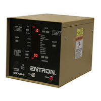
Entron EN1001 series Installation And Operation Manual (131 pages)
Brand:
Entron
| Category:
Welding Accessories
| Size: 1 MB
Table of Contents
Table of Contents
4
General Description
6
Standard Features
6
En1000/En1001 Control Panel Layout
8
Programmable Functions
9
Control Functions
9
Sequence Timed Parameters
11
Other Programmable Sequence Parameters
12
Installation
14
Installation Diagrams "S" Cabinet
14
Installation Diagrams "E" Cabinet
15
Installation Diagrams "T/D" and "L" Cabinet
16
Installation Diagrams, 'E' and 'T' Cabinet
17
Welding Transformer Primary Wiring
18
External Scr Contactor Wiring
18
Cooling Requirements for Contactors
20
General Operating Requirements
21
Operating Voltage
21
Fusing and Safe Operation
23
Terminal Strip Diagrams and Connections
24
Terminal Strip Input Ts1 on Pcb2
24
Terminal Strip Connections
26
Terminal Strip Ts1 Inside the Cabinet
28
Initiation
29
Initiation - Single Stage
29
Initiation - Two Stage
29
Other Terminal Strip Inputs
29
Non-Volatile Memory Error
31
Isolation Circuitry Description
33
Introduction to Data Programming
35
General Programming
35
Program Lockout Options
36
Program Lockout Key Option
36
Using Program Lockout Key for Error Clearing
36
Sequence Parameters Programming
37
Using Programming Shortcuts
38
Extended Functions
39
Identification Number
40
Seam Welding
41
Schedule Selection (Int./Ext.) and Anti-Tie down
42
Automatic Voltage Compensation and Monitoring
46
Clear All Functions
48
Back-Step / Temperature Limit Switch
49
Process Outputs
50
Beat Operation - Initiation Modes
55
Degree Delay
57
Power Factor Programming
58
Power Factor Measuring
58
Squeeze Delay
59
Blocking Delay
59
Constant Current Modes
60
Ratio or Range
61
Current Offset
62
Pin Lockout Mode
65
General Operating Instructions
66
Weld Sequence Example
66
Cycle Modes
67
Non Repeat
67
Repeat
68
Chain
68
Successive
70
Conditional Successive
71
Wait-Here
72
Slope Modes
73
Slope
73
Up Slope
74
Down Slope
74
Valve Modes
75
Stepper on En1000 Series Controls
76
Schedule Map
77
Stepper Programming
78
Schedule Initiation in Stepper Mode
80
Stepper Algorithm
81
Stepper Reset
83
Using Stepper as a Counter
84
Displaying Stepper Count During Operation
84
End of Stepper
84
Constant Current Operation
85
Introduction to Constant Current Operation
85
Constant Current Operation with Primary Sensor
90
Constant Current Operation with Secondary Hall-Effect Sensor
92
Constant Current Operation with Secondary Sensor
94
Sensor Selection Jumper Settings
96
Applications and Programming Examples
97
Spot Mode Examples
97
Seam Mode Examples
101
Brazing Application
104
Squeeze Delay Application
105
Retraction Application
106
Momentary Closure - [;!:!]
106
Maintained Closure - [H!=!]
107
Air over Oil Retraction - [;!:!]=[07]
108
Multiple Schedule Operation
113
Options for En1000 and En1001 Series Controls
114
Error Codes and Troubleshooting
116
Error Codes
116
Troubleshooting
118
Troubleshooting Guide
120
Block Diagram
122
Warranty and Service
123
Appendix A - Error Codes List
124
Appendix B - Introduction to Programming En1000 Series Controls
125
Advertisement
Related Products
Entron EN1000 series
Entron EN7000-TS
Entron EN7000
Entron EN6001
Entron EN7000v2
Entron EN7000v2-TS
Entron 01-70-27
Entron 01-70-28
Entron iPAK2
Entron iPAK2v2
Entron Categories
Controller
Control Unit
Welding Accessories
Measuring Instruments
Touchscreen
More Entron Manuals
Login
Sign In
OR
Sign in with Facebook
Sign in with Google
Upload manual
Upload from disk
Upload from URL