Entron EN1000 series Instructions Manual
Microprocessor based weld sequence controls with solid state thyristor contactors
Hide thumbs
Also See for EN1000 series:
- Instruction manual (61 pages) ,
- Installation and operation manual (131 pages)
Table of Contents
Advertisement
Appendix E – EN1000/EN1001 Bench Controls
Intended for use with firmware versions 619016-002Z and higher
Distributed by:
PRODUCTION ENGINEERING
1344 Woodman Dri
Dayton, Ohio 45432
888-654-WELD (9353)
sales@productionengineering.com
www.resistanceweldsupplies.com
INSTRUCTION MANUAL
700120S
EN1000/EN1001
SERIES CONTROLS
MICROPROCESSOR BASED
Weld Sequence Controls
Solid State Thyristor Contactors
INCLUDES:
Appendix F – EN1003 Controls
Cabinet Style
S
T/D/LS/LF/FP
E
D/T
C
IMU
With
Wiring Diagrams
EN1000
421180
421210
421212
421387
421498
421424
ENTRON Controls, LLC. • 700120S • Page 1
EN1001
421270
421269
421268
421377
421499
421423
Advertisement
Table of Contents
Troubleshooting

Related Manuals for Entron EN1000 series


Summary of Contents for Entron EN1000 series
- Page 1 421269 421212 421268 421387 421377 421498 421499 421424 421423 Intended for use with firmware versions 619016-002Z and higher Distributed by: PRODUCTION ENGINEERING 1344 Woodman Dri Dayton, Ohio 45432 888-654-WELD (9353) sales@productionengineering.com www.resistanceweldsupplies.com ENTRON Controls, LLC. • 700120S • Page 1...
- Page 2 THIS PAGE IS INTENTIONALLY BLANK Page 2 • 700120S • ENTRON Controls, LLC.
- Page 3 CAUTION READ THIS MANUAL COMPLETELY BEFORE ATTEMPTING TO INSTALL OR OPERATE THIS CONTROL ENTRON Controls, LLC., reserves the right to alter the contents of this manual without previous notice. ENTRON Controls, LLC. Greer, South Carolina 29650...
-
Page 4: Table Of Contents
POWER FACTOR MEASURING .................. 5.4.12 SQUEEZE DELAY ......................5.4.13 BLOCKING DELAY ....................... 5.4.14 TURNS RATIO ......................5.4.15 CONSTANT CURRENT MODES .................. 5.4.16 RANGE .......................... 5.4.17 CURRENT OFFSET ..................... 5.4.18 PIN LOCKOUT MODE ....................Page 4 • 700120S • ENTRON Controls, LLC. - Page 5 BEFORE 619016-001R ....................9.0 APPLICATIONS AND PROGRAMMING EXAMPLES ........SPOT MODE EXAMPLES ..................106 9.1.1 SPOT WITH REPEAT MODE ..................9.1.2 PULSATION WITH SUCCESSIVE MODE ..............9.1.3 QUENCH-TEMPER WITH CHAINED MODE ............ENTRON Controls, LLC. • 700120S • Page 5...
- Page 6 EN1000/EN1001 BENCH CONTROLS ............154 APPENDIX F EN1003 THREE PHASE DC CONTROLS ........... 158 APPENDIX G EN1000 SERIES RESPONSE TIMES ............161 APPENDIX H IMU MOUNTING OPTIONS ................. 162 APPENDIX I PROGRAMMING WORKSHEETS ............... 164 Page 6 • 700120S • ENTRON Controls, LLC.
- Page 7 FIGURE 7-2 SELECT WELD/HEAT ....................89 FIGURE 7-3 PROGRAM WELD COUNT ..................89 FIGURE 7-4 PROGRAM LAST STEP ................... 90 FIGURE 7-5 PROGRAM LAST COUNT ..................90 FIGURE 7-6 ALGORITHM ......................93 ENTRON Controls, LLC. • 700120S • Page 7...
- Page 8 PROGRAMMING FOR STEPPER MODE 02 02 02 02 02 ............94 TABLE 7-5 TABLE 8-1 OPERATING RANGES FOR PRESET-RANGE SELECTION WITH ROGOWSKI COIL ....................99 TABLE 9-1 EXTERNAL SCHEDULE SELECT WITH FS7 AND FS11 ........122 Page 8 • 700120S • ENTRON Controls, LLC.
-
Page 9: General Description
500 Hz to 2000 Hz operating frequency rating. The EN1001 differs from EN1000 as it has a Constant Current mode of operation, see Section 5.4.15 and Section 8.0. Figure 1-1. EN1000/EN1001 System ENTRON Controls, LLC. • 700120S • Page 9... -
Page 10: Standard Features
When external valve power is used, 24-240 VAC or 24 VDC, valve transformer must be disconnected at TS3-VL1 and TS3-VL2. Caution must be used to properly insulate the wires from T3-X1 and T3-X2 leads after removing from TS3. Page 10 • 700120S • ENTRON Controls, LLC. -
Page 11: Control Panel Layout
* For operator convenience, codes for SLOPE MODE and CYCLE MODE functions are printed on the left side of the Control Panel. On EN1000 Control Panel layout, there is no added text for CONSTANT CURRENT modes. ENTRON Controls, LLC. • 700120S • Page 11... -
Page 12: Programmable Functions
As the button is pressed, the corresponding LED will light up to indicate the parameter data in the DATA display. Holding the SELECT push button momentarily will reverse the direction of the LED movement when the button is released. Page 12 • 700120S • ENTRON Controls, LLC. - Page 13 Rotate the key 45 degrees clockwise and hold, while holding the key in this position, press and release the PROGRAM/OPERATE push button, then release the key. The OPERATE LED will now turn off and the PROGRAM LED will turn on, indicating programmability of all functions. ENTRON Controls, LLC. • 700120S • Page 13...
-
Page 14: Sequence Timed Parameters
COOL COUNT (14) – The time between heat IMPULSES (in multiple impulse welding). SLOPE COUNT (18) – The number of additional WELD cycles during which PERCENT CURRENT increases or decreases to achieve SLOPE (gradual increase or decrease in current). Page 14 • 700120S • ENTRON Controls, LLC. -
Page 15: Other Programmable Sequence Parameters
FS7 or FS11 and schedule 10 or 20 will be sequenced (see Section 6.2.6) NOTICE The CYCLE MODE and SLOPE MODE function codes are printed on the Control Panel, adjacent to the ENTER push button, for operator convenience. ENTRON Controls, LLC. • 700120S • Page 15... -
Page 16: Table 2-3 Valve Codes
LEDs (29, 30, 31) will indicate the selected valve(s). The valve output will not be energized while in PROGRAM mode. NOTICE The VALVE code indicated above can be programmed for different features such as PROCESS OUTPUT (see Section 5.4.7). Page 16 • 700120S • ENTRON Controls, LLC. -
Page 17: Installation
The installation and mounting diagrams for “S” Cabinet are shown in Figure 3-1. Available contactors for “S” Cabinet – 150A, 300A, and 1200A. Figure 3-1. Installation and mounting diagrams for Style “S” Cabinet ENTRON Controls, LLC. • 700120S • Page 17... -
Page 18: Installation And Mounting Diagrams - "E" Cabinet
Style “E” Cabinet installation and mounting diagrams are shown in Figures 3-2, 3-3 and 3-4. Figure 3-2. Installation of Style “E” Figure 3-3. Installation of Style “E” Cabinet – 300A & 1200A Contactor Cabinet – 1800/2200/3200A Contactor Figure 3-4. Mechanical mounting diagram for “E” Cabinet Page 18 • 700120S • ENTRON Controls, LLC. -
Page 19: Installation And Mounting Diagrams - "T/D" And "L" Cabinet
Figure 3-5. Installation of Style “T/D” and Figure 3-6. Installation of Style “T/D” and “L” Cabinets – 1200A Contactor “L” Cabinets – 1800/2200/3200A Contactor Figure 3-7. Mechanical mounting diagram for “T/D” and “L” Cabinets ENTRON Controls, LLC. • 700120S • Page 19... -
Page 20: Installation And Mounting Diagrams - "C" Cabinet
TERMINAL STRIP TS1 CUTOUT THRU REAR PANEL TO 1200A REAR OF CABINET CONTACTOR FOR CUSTOMER WIRING WATER WATER Figure 3-8. Installation diagram for Style “C” Cabinet Figure 3-9. Mounting diagrams for Style “C” Cabinet Page 20 • 700120S • ENTRON Controls, LLC. -
Page 21: Installation And Mounting Diagrams - Flat Plate And Imu
(IMU) component forms. Installation and mounting diagrams for these controls are shown in Figures 3-10, 3-11, 3-12, and 3-13. Figure 3-10. Installation and mounting for 11x11 Flat Plate Figure 3-11. Installation and mounting for 21x21 Flat Plate ENTRON Controls, LLC. • 700120S • Page 21... -
Page 22: Figure 3-12 Installation And Mounting Diagrams For 13X19 Flat Plate
3.5 INSTALLATION AND MOUNTING DIAGRAMS – FLAT PLATE AND IMU (cont.) Figure 3-12. Installation and mounting for 13x19 Flat Plate Figure 3-13. Installation and mounting for Integrated Modular Unit See Appendix H for more detailed installation information for IMU. Page 22 • 700120S • ENTRON Controls, LLC. -
Page 23: Welding Transformer Primary Wiring
Connect to the current coil (EN1001 only ) J12-B J12-W Connect to the current coil (EN1001 only ) For more information, refer to appropriate Wiring Diagram (see front page). NOTICE Do not over tighten J5 or J6. ENTRON Controls, LLC. • 700120S • Page 23... -
Page 24: Figure 3-14 External Scr Contactor Connections
3.7 EXTERNAL SCR CONTACTOR WIRING (cont.) Figure 3-14. External SCR Contactor connections Page 24 • 700120S • ENTRON Controls, LLC. -
Page 25: Contactor Specifications
Duty Cycle is the percent of the time the weld current is on. A convenient formula for calculating Duty Cycle is: Weld Time (in Cycles) x Number of welds per minute % Duty Cycle = ENTRON Controls, LLC. • 700120S • Page 25... -
Page 26: Figure 3-15 Demand Current Vs. Percent Duty Cycle
Example 1 Figure 3-15. Demand Current vs. Percent Duty Cycle NOTICE Ignition tubes for reference only. SCR Contactors available for EN1000/EN1001 are: 150A, 300A, 1200A, 1800A, 2200A, and 3200A (indicated by arrows). Page 26 • 700120S • ENTRON Controls, LLC. -
Page 27: Cooling Requirements For Contactors
An open drain is recommended for best operation. If a closed return system is used, be sure return line is properly sized so that back pressure will not reduce water flow below recommendations. A sight flow indicator is recommended. ENTRON Controls, LLC. • 700120S • Page 27... -
Page 28: General Operating Requirements
For 380 VAC Operation – CONTACT FACTORY For 575 VAC Operation – FACTORY WIRED ONLY NO CALIBRATION OR CHANGE REQUIRED FOR OPERATION ON EITHER 50 OR 60 Hz. Figure 4-1. Voltage operation jumpers settings Page 28 • 700120S • ENTRON Controls, LLC. -
Page 29: Figure 4-2 Valve Transformer Jumpers Settings
Jumper H1/H3 and H2/H4 • Jumper CTH1/CTH3 and CTH2/CTH4 Valve Transformer: • Jumper H1/H3 and H2/H4 480 Volt Operation Jumpers Terminal Strip TS1: • Jumper H3/H2 • Jumper CTH3/CTH2 Valve Transformer: • Jumper H3/H2 ENTRON Controls, LLC. • 700120S • Page 29... -
Page 30: Fusing And Safe Operation
USE ONLY THE FUSE TYPE SPECIFIED TO MAINTAIN SAFE OPERATION. Observe the WARNING, DANGER and CAUTION labels affixed to the control to maintain safe operation. Some of them are shown in Figure 4-3. Figure 4-3. Warning, Danger and Caution labels Page 30 • 700120S • ENTRON Controls, LLC. -
Page 31: Terminal Strip Diagrams And Connections
4.3 TERMINAL STRIP DIAGRAMS AND CONNECTIONS 4.3.1 TERMINAL STRIP TS1/PCB2 See front page for appropriate Wiring Diagram. Figure 4-4. Terminal Strip/Firing Board For most current revision of the component placement on this board, see Figure 4-5. ENTRON Controls, LLC. • 700120S • Page 31... -
Page 32: Figure 4-5 Component Placement On New Terminal Strip/Firing Board
When Valve Terminals are loaded, these voltages will disappear. Figure 4-5. Component placement on new Terminal Strip/Firing Board For hookup and all terminal connections, see Figure 4-4. Page 32 • 700120S • ENTRON Controls, LLC. -
Page 33: Terminal Strip Connections
TS1-FS11/SS3 and TS1-FS3. As shown in Figure 9-16, these switches can now be used as pointers to one of four schedules. TS1-FS3 is then used to initiate the schedule pointed to. See Table 5-1 in Section 5.4.3. ENTRON Controls, LLC. • 700120S • Page 33... - Page 34 Used to connect one side of a Temperature Limit Switch. When used, remove jumper and install a normally closed Temperature Limit Switch between TLS1/AUX1 and TS1-GND terminals. This terminal may also be used for an auxiliary function. Page 34 • 700120S • ENTRON Controls, LLC.
-
Page 35: Terminal Strip Ts1 Inside The Cabinet
Used as Valve Power Supply Input and other side of Jumper JB. TS3-VL2 Used as Valve Power Supply Input. 4.3.3 TERMINAL STRIP TS1 INSIDE THE CABINET See front page for appropriate Wiring Diagram. Figure 4-6. Terminal Strip for “T/D” Cabinet ENTRON Controls, LLC. • 700120S • Page 35... -
Page 36: Initiation
NO WELD mode even if WELD LED is illuminated. NOTICE If a Weld/No Weld Switch is not used, place a jumper (factory installed) between TS1-NW1and TS1-GND. Weld/No Weld Switch is not supplied with the control. Page 36 • 700120S • ENTRON Controls, LLC. -
Page 37: Figure 4-8 Other Inputs On Terminal Strip Ts1
Upon release of the switch, it must be re-initiated by closing the Pilot Switch. NOTICE If the Emergency Stop Switch is not used, place a jumper (factory installed) between TS1-ES1 and TS1-GND. Emergency Stop Switch is not supplied with the control. ENTRON Controls, LLC. • 700120S • Page 37... -
Page 38: Non-Volatile Memory Error
4.6 NON-VOLATILE MEMORY ERROR All ENTRON microprocessor based controls make extensive use of non-volatile memory devices for parameter data storage. Although safety features (control relays and opto-isolation) are in place to insure high voltage spikes do not appear on low voltage circuits, non-volatile memory devices can sometimes be affected by improper hookup, electrical disturbances generated in other equipment operating nearby, or in the welding machine itself. -
Page 39: Figure 4-10 Wrong Routing Of Low And High Voltage Wires
NOTICE Avoid routing high and low voltage wires parallel to each other to eliminate coupling adjacent signals which may cause irregular operation. ENTRON Controls, LLC. • 700120S • Page 39... -
Page 40: Isolation Circuitry Description
4.7 ISOLATION CIRCUITRY DESCRIPTION The EN1000 Series Controls are microprocessor-based resistance welding controls that incorporate circuitry designed to prevent any output from the control due to spurious or unexpected or false conditions or failure of circuit components. The intent of this section is to explain how the circuitry accomplishes this isolation. - Page 41 Through a PROCESS OUTPUT system, the EN1000 Series Controls can be programmed so that if the 20 volt energizing voltage for the isolation relays appears in the absence of an initiation, or if the SCR contactor conducts current at any time other than when programmed, an output voltage will appear at the Valve 3 terminals.
-
Page 42: Introduction To Data Programming
100; press and hold to increment by 1000. 5. Press the ENTER push button to store data from the DATA display into non-volatile memory. As ENTER is pressed, the DATA display will blink and then remain steady. Page 42 • 700120S • ENTRON Controls, LLC. -
Page 43: Program Lockout Options
ERROR CODES (all codes from 17 17 17 17 17 to 35 35 35 35 35, 37 37 37 37 37, H.i. H.i. H.i. H.i. H.i. and L.o. L.o. L.o. L.o. L.o.). ENTRON Controls, LLC. • 700120S • Page 43... -
Page 44: Sequence (Schedule) Parameters Programming
Section 8.0. + See Section 8.3.2 for programming information. Times for WELD, COOL, SLOPE COUNT and all other timed sequence parameters (SQUEEZE, HOLD, OFF) are based on 60 Hz or 50 Hz frequency. Page 44 • 700120S • ENTRON Controls, LLC. -
Page 45: Using Programming Shortcuts
FROM CONTROL 1. Remove all power to the control. 2. Press and hold the PROGRAM/OPERATE push button. 3. Reapply power to the control. All EXTENDED FUNCTIONS parameters in the control have been erased. ENTRON Controls, LLC. • 700120S • Page 45... -
Page 46: Extended Functions
DATA display will show the current value of that selection. Figure 5-7. Viewing EXTENDED FUNCTIONS To exit the EXTENDED FUNCTION mode, press SELECT to advance the FUNCTION indicator LED one more time. Page 46 • 700120S • ENTRON Controls, LLC. -
Page 47: Identification Number
1. Put the control in PROGRAM mode. 2. Use SELECT to find EF EF EF EF EF. 3. Use the SCHEDULE push buttons to scroll through EXTENDED FUNCTIONS and find S.E. S.E. S.E. S.E. S.E. ENTRON Controls, LLC. • 700120S • Page 47... - Page 48 WARNING Care MUST be taken to minimize the overheating of internal components when in the SEAM mode. Correct transformer power dissipation (sizing) and welding control capability are essential to avoid component overheating. Page 48 • 700120S • ENTRON Controls, LLC.
- Page 49 S.E. S.E. S.E. S.E.=54 54 54 54 54, then during first five weld cycles, control will only perform current measurement without any compensation, and on sixth cycle it will start to compensate. ENTRON Controls, LLC. • 700120S • Page 49...
-
Page 50: Schedule Select
S.S.=01 01 01 01 01 for EXTERNAL SCHEDULE SELECT S.S. S.S. S.S. S.S. S.S. S.S. S.S.=03 03 03 03 03 for S49 EXTERNAL BINARY SCHEDULE SELECT 5. Press the ENTER push button. Page 50 • 700120S • ENTRON Controls, LLC. -
Page 51: Table 5-1 External Schedule Select With Fs7 And Fs11
In this mode, the operator cannot select schedules using the Front Panel in OPERATE mode and can only initiate using TS1-FS3. Binary selects TS1-FS7 and TS1-FS11 must be closed before initiation of TS1-FS3 and be opened after sequence is started or completed. ENTRON Controls, LLC. • 700120S • Page 51... -
Page 52: Figure 5-8 Dual Two-Stage Foot Switch Initiation
Figure 5-9. The diode assembly may be substituted with most any silicon diode. Figure 5-9. Multiple two-stage foot * Similar connections can be used with S49 Option (see switch initiation EXTERNAL BINARY SELECT Section). Page 52 • 700120S • ENTRON Controls, LLC. - Page 53 In order to program this EXTENDED FUNCTION parameter S.S. S.S. present and connected to the Control Board. The option consists of a J4 ribbon cable, an additional PCB 410329-004 with six binary schedule select inputs and Control Board 600572-009 (EN1001) ENTRON Controls, LLC. • 700120S • Page 53...
-
Page 54: Figure 5-12 Switch Closure Connections
Table 5-2. S49 EXTERNAL SCHEDULE SELECT DECIMAL (SCHEDULE) TO BINARY (TS12-SS1 through TS12-SS32) SCHED SS16 SS32 SCHED SS16 SS32 1 = CLOSED 0 = OPEN TS12-SS1 through TS12-SS32 require 24 VDC at 50 mA contacts Page 54 • 700120S • ENTRON Controls, LLC. -
Page 55: Figure 5-13 Multiple Pilot Switch Connections
Table 5-3. Stepper selection using SS1, SS2, SS4, SS8 input is necessary for each STEPPER SCHEDULE INITIATION stepper. This helps economize TS1-FS3 on PLC outputs otherwise TS1-FS3 TS1-FS3 necessary to select schedule for TS1-FS3 any of five steppers. TS1-FS3 ENTRON Controls, LLC. • 700120S • Page 55... - Page 56 01 whenever appropriate during the weld. It can just as easily select 10 before beginning the weld, and switch to 11 whenever appropriate during that weld. Ultimately, the application dictates the schedule selected. Page 56 • 700120S • ENTRON Controls, LLC.
-
Page 57: Automatic Voltage Compensation And Monitoring
For example, if the C.C. C.C. C.C. until the line voltage is steady state line voltage is approximately 480 VAC, do not program C.C. C.C. as close to 480 VAC as possible. ENTRON Controls, LLC. • 700120S • Page 57... - Page 58 Display error, turn on Valve 3 for 30 cycles (0.5 seconds) and continue with sequence. P P P P P .O. .O. .O. .O. .O.=14 14 14 14 14 Display error, turn on Valve 3, and stop the sequence. Page 58 • 700120S • ENTRON Controls, LLC.
-
Page 59: Clear All Functions
All EXTENDED FUNCTIONS parameters in the control have been erased. NOTICE After firmware updates in the field, a one-time CLEAR ALL is required when upgrading to a new version of firmware on ALL older Control Boards. ENTRON Controls, LLC. • 700120S • Page 59... -
Page 60: Back-Step / Temperature Limit Switch
TEMPERATURE LIMIT SWITCH mode. If the control is using the RETRACTION PROCESS OUTPUT (P P P P P .O. .O. .O. .O. .O.=08 08 08 08 08), terminal TS1-TLS1/AUX1 is used as an input, thus BACK-STEP is not available. Page 60 • 700120S • ENTRON Controls, LLC. -
Page 61: Process Outputs
The jumper between TS3-1 and TS3-VL1 is necessary to bypass the Valve Control Relay normally incorporated in the standard operation of Valve 3. Table 5-6 summarizes all PROCESS OUTPUT codes. Detailed descriptions of each PROCESS OUTPUT follow the table. ENTRON Controls, LLC. • 700120S • Page 61... -
Page 62: Table 5-6 Process Output Codes And Descriptions
WELD mode and closed NW1-GND input on TS1 reserved ON if ERROR %( (IPSC or IPS error) occurs ON if ERROR %( (IPSC or IPS error) occurs at the end of weld * ONLY available with EN1001 Controls. Page 62 • 700120S • ENTRON Controls, LLC. - Page 63 PLC receives this signal and halts the subsequent process. Note that this signal will be active if the control is in NO WELD or in PROGRAM mode. ENTRON Controls, LLC. • 700120S • Page 63...
- Page 64 ON after SQUEEZE and during WELD – Valve 3 output will be ON after SQUEEZE and during application of WELD current, regardless of whether control is in WELD or NO WELD mode. Can be used with welder interlocks (see Instruction Manual 700200). Page 64 • 700120S • ENTRON Controls, LLC.
- Page 65 WELD portion of the weld sequence and turns the Valve 3 ON if the TRIGGER value for PRESSURE/FORCE/CURRENT is not reached. The TRIGGER values must be programmed within a valid range. ENTRON Controls, LLC. • 700120S • Page 65...
-
Page 66: Beat Operation Initiation Modes
Allow enough SQUEEZE time for the operator to check alignment during SQUEEZE and open the pilot circuit before the WELD time begins. This will allow the operator time to reposition the part if the alignment is not proper. Page 66 • 700120S • ENTRON Controls, LLC. -
Page 67: Figure 5-16 Using Light Curtain
Figure 5-16, are used to activate the Emergency Stop circuit. Figure 5-16. Using light curtain * This mode will not affect BEAT operation. ENTRON Controls, LLC. • 700120S • Page 67... -
Page 68: 87° Delay
01 01 01 01 01 = 87° DELAY is enabled – default (factory setting) 5. Press ENTER. NOTICE 87° DELAY ENABLE or DISABLE is only operational in MANUAL POWER FACTOR mode of operation (see Section 5.4.10). Page 68 • 700120S • ENTRON Controls, LLC. -
Page 69: Manual Power Factor Programming
At this point, after the weld is complete, the machine’s POWER FACTOR will be shown in the DATA display (see Section 5.4.10). NOTICE When measuring the POWER FACTOR, the displayed POWER FACTOR corresponds to the last weld made by the control. ENTRON Controls, LLC. • 700120S • Page 69... -
Page 70: Squeeze Delay
MONITORING mode, the control only measures the primary current from the sensor, and then calculates the secondary current by the following equation: Secondary Current = Primary Current × Turns Ratio of transformer Page 70 • 700120S • ENTRON Controls, LLC. -
Page 71: Constant Current Modes
Secondary Rogowski Coil: S6 or S10 Secondary Compensation Auto Range up to 99.99 kA Secondary Monitoring Auto Range up to 99.99 kA Secondary Compensation 2 to 99.99 kA Secondary Monitoring 2 to 99.99 kA ENTRON Controls, LLC. • 700120S • Page 71... -
Page 72: Range
.A. .A. will cause overshooting or poor compensation quality during the current compensation process. More information about r r r r r .A. .A. .A. .A. .A. setting is described in Section 8.2. Page 72 • 700120S • ENTRON Controls, LLC. -
Page 73: Current Offset
C.O. C.O. Where: CURRENT OFFSET is disabled C.O. C.O. C.O.=21 21 21 21 21 to 39 39 39 39 39 CURRENT OFFSET is enabled for ALL SCHEDULES C.O. C.O. 5. Press ENTER. ENTRON Controls, LLC. • 700120S • Page 73... - Page 74 PROGRAM mode and following normal programming procedures. In PROGRAM mode, the display will flash between BASE CURRENT and OFFSET CURRENT value. PERCENT CURRENT is the only weld schedule parameter that is changed whenever a CURRENT OFFSET value is used. Page 74 • 700120S • ENTRON Controls, LLC.
- Page 75 For example: For an original BASE CURRENT value of 14.00 kA and maximum RMS is 20.00 kA, a new value may be from 13.00 kA to 15.00 kA (because 5% of 20.00 kA is 01.00 kA). ENTRON Controls, LLC. • 700120S • Page 75...
-
Page 76: Pin Lockout Mode
C.A.=02 02 02 02 02, or by pressing and holding PROGRAM/OPERATE push button during power-up or after Emergency Stop reset. This may be also very useful whenever the PIN is lost. NOTICE The control is shipped from the factory in the disabled PIN LOCKOUT mode. Page 76 • 700120S • ENTRON Controls, LLC. -
Page 77: General Operating Instructions
CAUTION KEEP HANDS, ARMS, OTHER PORTIONS OF THE BODY, CLOTHING, AND TOOLS AWAY FROM THE MOVING PARTS OF THE MACHINE. ENTRON Controls, LLC. • 700120S • Page 77... -
Page 78: Cycle Modes
Upon initiation, the programmed valve is energized at the beginning of SQUEEZE. If the Pressure Switch is open, the control counts through the SQUEEZE time but does not begin counting Figure 6-1. NON-REPEAT sequence Page 78 • 700120S • ENTRON Controls, LLC. -
Page 79: Repeat
01 01 01 01 01 (REPEAT), or 03 03 03 03 03 (SUCCESSIVE). If CYCLE MODE 01 01 01 01 01 is used in the last schedule of a CHAINED sequence, the entire chain will be repeated if the initiation is held closed. ENTRON Controls, LLC. • 700120S • Page 79... -
Page 80: Figure 6-3 Chained Sequence
The sequence will start over at the initiated sequence and continue as explained in CHAINED mode. 02 02 02 02 02 CHAINED: The SCHEDULE display will increment by one and continue as explained in CHAINED mode. Page 80 • 700120S • ENTRON Controls, LLC. -
Page 81: Successive
An initiation at this point would start schedule 02. After schedule 02 was completed, the SCHEDULE display would then increment to schedule 03 (flashing). After the next initiation, schedule 03 will be completed and the SCHEDULE display will again show schedule 01. ENTRON Controls, LLC. • 700120S • Page 81... -
Page 82: Conditional Successive
When the operator closes the foot switch again, the control activates the following CHAINED schedule immediately. During the second schedule, the control adds a second valve to the first, the clamp valve. Page 82 • 700120S • ENTRON Controls, LLC. -
Page 83: Wait-Here
FS7 or FS11 initiation. When the FS7 or FS11 initiation input closes, the control will continue by selecting schedule 10 or 20, respectively, and executing it as programmed whether it is a SPOT or REPEAT or CHAINED sequence. ENTRON Controls, LLC. • 700120S • Page 83... -
Page 84: Slope Modes
UPSLOPE are programmed in SLOPE COUNT, for SLOPE MODE 01 01 01 01 01 or 02 02 02 02 02, and the number of WELD cycles is 21, the total amount of WELD time is 35 cycles. Page 84 • 700120S • ENTRON Controls, LLC. -
Page 85: No Slope
6.3 SLOPE MODES (cont.) The ENTRON UPSLOPE and DOWNSLOPE functions are sequential. The UPSLOPE COUNT and DOWNSLOPE COUNT setting and the WELD count times are independent of each other. Adjusting either of the SLOPE COUNTS or WELD count does not affect the setting or operation of the other switch setting. -
Page 86: Valve Modes
The VALVE MODES indicated within the valve selection chart may differ with the use of PROCESS OUTPUTS. Refer to Section 5.4.7 of this manual for further information on the use of Valve 3 as a PROCESS OUTPUT indicator. Page 86 • 700120S • ENTRON Controls, LLC. -
Page 87: Stepper On En1000/En1001 Series Controls
WELD time and weld CURRENT must be programmed, and control must be in the WELD mode (External Weld/No Weld Switch, if used, must be closed and Front Panel WELD/NO WELD indicator LED must be in WELD mode). ENTRON Controls, LLC. • 700120S • Page 87... -
Page 88: Schedule Map
For STEPPER mode 02 02 02 02 02, the same schedule map is used as in mode 01 01 01 01 01, except that only one stepper counter exists with all schedules from 00 to 49, with maximum of 50 steps. Page 88 • 700120S • ENTRON Controls, LLC. -
Page 89: Stepper Programming
1. Using the SCHEDULE push buttons, set the first schedule for desired stepper; e.g., for stepper A, first schedule is 00. 2. Put the control in PROGRAM mode by clicking PROGRAM/OPERATE push button. Figure 7-2. Select WELD/HEAT Figure 7-3. Program WELD COUNT ENTRON Controls, LLC. • 700120S • Page 89... -
Page 90: Last Step And Last Count Programming
This value will be reset or reprogrammed after resetting the stepper. 7. Put the control back in OPERATE mode. Figure 7-4. Program LAST STEP Figure 7-5. Program LAST COUNT Page 90 • 700120S • ENTRON Controls, LLC. -
Page 91: Quick Setup Instructions For Stepper
S.t.=02 02 02 02 02 with multiple steppers, all steppers must be reset. When using S.t. S.t. To reset stepper, repeat steps 10 and 11. Control must be in PROGRAM mode for step 10. ENTRON Controls, LLC. • 700120S • Page 91... -
Page 92: Sequence (Schedule) Initiation In Stepper Mode
S.S.=03 03 03 03 03) after S.S. respectively. But, when S49 Option is used for EXTERNAL BINARY SELECT (S.S. FS7 initiation, the control will execute any selected schedule, instead of schedule 10. Page 92 • 700120S • ENTRON Controls, LLC. -
Page 93: Stepper Operation
7.4 STEPPER OPERATION 7.4.1 OPERATION ALGORITHM FOR STEPPER MODE S.t. S.t. S.t. S.t. S.t.=01 01 01 01 01 Figure 7-6. Algorithm ENTRON Controls, LLC. • 700120S • Page 93... -
Page 94: Stepper Operation For Stepper Mode S.t. S.t.=02 02 02 02 02
L.S. L.S.=00 00 00 00 00 in this example, and LAST COUNT L.C. L.S. L.C. L.C. L.C.=0325 L.C. 0325 0325 0325 0325, no matter which schedule is dialed on Front Panel display. Page 94 • 700120S • ENTRON Controls, LLC. -
Page 95: Stepper Reset
… … MODE DESCRIPTION STEP COUNT G!" 0325 Step 1 0400 Step 2 G!$ 0450 Step 3 G!% 0010 Pre-warning step, adding Valve 2 output G!& 0000 RESET command (all other parameters="") ENTRON Controls, LLC. • 700120S • Page 95... -
Page 96: Stepper Reset Using External Switch Input
.O. .O. is programmed to 10 10 10 10 10 or 17 17 17 17 17, PROCESS OUTPUT valve or Valve 3 will be active as long as message S.t. S.t. S.t. S.t. E.n.d. S.t. E.n.d. E.n.d. E.n.d. E.n.d. is flashing on displays. Page 96 • 700120S • ENTRON Controls, LLC. -
Page 97: Constant Current Operation (En1001 Only)
8.1 HARDWARE SETUP The EN1001 Control can be operated with the following types of Current Sensors: 1. Primary Current Transformer 2. Secondary Rogowski Coil ENTRON Controls, LLC. • 700120S • Page 97... -
Page 98: Software Parameters Setup
.., C.r C.r.., and r r r r r .A. .A. .A. .A. .A. are described in Sections 5.4.14, 5.4.15 and 5.4.16. Page 98 • 700120S • ENTRON Controls, LLC. -
Page 99: Secondary Preset-Range Compensation Or Monitoring Mode With Rogowski Coil
PRIMARY PRESET-RANGE COMPENSATION mode. When the control operates in this COMPENSATION mode, the value of CURRENT setting in the weld schedules should be input as the desired secondary current in [kA] value. ENTRON Controls, LLC. • 700120S • Page 99... -
Page 100: Secondary Auto-Range Compensation Or Monitoring Mode With Rogowski Coil
The learning-type setup process is described in Section 8.4. Normally these modes are only used when the current range of control is unavailable. Page 100 • 700120S • ENTRON Controls, LLC. -
Page 101: Displaying Current After Weld Sequence
To show PERCENT, simply press the DATA 1s push button. To show last measured RMS CURRENT in [kA], simply press the DATA 10s push button. To clear display, press any other push button. ENTRON Controls, LLC. • 700120S • Page 101... -
Page 102: Using Constant Current Process Outputs
CURRENT value, the control will flash L.o. L.o. L.o. L.o. or H.i. L.o. H.i. H.i. H.i. (depending on the case). In addition, H.i. the control will turn Valve 3 ON for 0.5 seconds (30 cycles). Page 102 • 700120S • ENTRON Controls, LLC. -
Page 103: Setting Limit Window For Constant Current
Current Sensor, then set the gain for the embedded amplifier. Follow the steps outlined in either of the next two sections (8.4.1 or 8.4.2) depending on which matches your control’s specifications. ENTRON Controls, LLC. • 700120S • Page 103... -
Page 104: Setting Up Current Regulator
S.E. S.E. to OPERATE mode. NOTICE Before running setup, make sure jumper on back side of Control Board is set in proper position (see Figure 8-3). Figure 8-3. Jumper settings Page 104 • 700120S • ENTRON Controls, LLC. -
Page 105: Setting Up Current Regulator - Boards W/Proms Before 619016-001R
6. Release the initiation switch. The control is now set up and ready to operate. PERCENT CURRENT must be re- programmed now as a four-digit number (example: 80% = 0080 0080 0080 0080 0080). ENTRON Controls, LLC. • 700120S • Page 105... -
Page 106: Applications And Programming Examples
Schedule 01 uses Valve 1, schedule 02 uses Valve 2. WELD/ PERCENT VALVE CYCLE SLOPE SLOPE SCHEDULE SQUEEZE HOLD IMPULSES COOL HEAT CURRENT MODE MODE MODE COUNT Figure 9-2. PULSATION with SUCCESSIVE mode Page 106 • 700120S • ENTRON Controls, LLC. -
Page 107: Quench-Temper With Chained Mode
Valve 1 output is used for this example. WELD/ PERCENT VALVE CYCLE SLOPE SLOPE SCHEDULE SQUEEZE HOLD IMPULSES COOL HEAT CURRENT MODE MODE MODE COUNT Figure 9-4. UPSLOPE and DOWNSLOPE with CHAINED mode ENTRON Controls, LLC. • 700120S • Page 107... -
Page 108: Butt Weld With Chained Mode
HOLD time of the first schedule or into SQUEEZE time of the second schedule. WELD/ PERCENT VALVE CYCLE SLOPE SLOPE SCHEDULE SQUEEZE HOLD IMPULSES COOL HEAT CURRENT MODE MODE MODE COUNT Page 108 • 700120S • ENTRON Controls, LLC. -
Page 109: Figure 9-6 Forge Delay With Chained Mode
Other combinations of weld schedules may be combined to create other forging schedules. For example, it would be possible to use UPSLOPE in the first sequence and PULSATION in the second sequence. ENTRON Controls, LLC. • 700120S • Page 109... -
Page 110: Seam Mode Examples
SEAM or ROLL SPOT, the programmed SQUEEZE time will only be in effect upon initiation. S.E. S.E. To return the control back to SPOT mode, the EXTENDED FUNCTION S.E. S.E. S.E. must be programmed to 00 00 00 00 00 (see Section 5.4.2). Page 110 • 700120S • ENTRON Controls, LLC. -
Page 111: Seam Mode S.e. S.e.=06 06 06 06 06
VALVE CYCLE SLOPE SLOPE SCHEDULE SQUEEZE HOLD IMPULSES COOL HEAT CURRENT MODE MODE MODE COUNT WELD1 WELD2 01 slope 02 seq.A 03 seq.B 04 seq.C 05 seq.D Figure 9-9. NON-BEAT SEAM mode ENTRON Controls, LLC. • 700120S • Page 111... -
Page 112: Brazing Application
Current may be turned on and off in this manner as many times as desired by operator. When First Stage is opened, electrodes retract. Figure 9-10. Using Two Stage initiation in BRAZING mode Page 112 • 700120S • ENTRON Controls, LLC. -
Page 113: Squeeze Delay Application
7. Adjust SQUEEZE and OFF times to allow the electrodes to open only a short distance between repeated welding sequences. 8. Press PROGRAM/OPERATE push button to put the control in OPERATE mode. ENTRON Controls, LLC. • 700120S • Page 113... -
Page 114: Retraction Application
TS1-TLS1/AUX1 from TS1-GND. The Control Panel indication of Valve 3 output (retraction valve) will not indicate the status of PROCESS OUTPUT. Page 114 • 700120S • ENTRON Controls, LLC. -
Page 115: Maintained Closure
This feature, simple as its operation may be, will help users implement this type of retraction without putting high voltage on one pole and/or in the same conduit as the low voltage foot switch wiring. ENTRON Controls, LLC. • 700120S • Page 115... -
Page 116: Figure 9-13 Maintained Closure Retraction Connections
5. Use the DATA push buttons to display 09 09 09 09 09 in DATA display. 6. Press ENTER push button to store the data. 7. Open the retraction switch held closed in Step 1. 8. Press PROGRAM/OPERATE push button to put the control in OPERATE mode. Page 116 • 700120S • ENTRON Controls, LLC. -
Page 117: Air Over Oil Retraction
The blocking valve will turn on immediately at the end of a programmed ADVANCE STOP time. Travel distance will depend on SQUEEZE DELAY plus ADVANCE STOP. In addition, inertia of the gun, oil pressure, etc., may influence travel distance. ENTRON Controls, LLC. • 700120S • Page 117... -
Page 118: Figure 9-14 Air Over Oil Retraction Connections
Since this valve may now be activated without energizing the control relay, care MUST be taken to insure safe operation. Figure 9-14. Air Over Oil Retraction connections Page 118 • 700120S • ENTRON Controls, LLC. - Page 119 00) and intensify (schedule 01) valve sequencing. NOTICE Schedule 00 uses Valve 1 to activate the extend valve for 20 cycles. WELD/ PERCENT VALVE CYCLE SLOPE SLOPE SCHEDULE SQUEEZE HOLD IMPULSES COOL HEAT CURRENT MODE MODE MODE COUNT ENTRON Controls, LLC. • 700120S • Page 119...
- Page 120 After a momentary closure of FS1, SQUEEZE DELAY is followed by ADVANCE STOP before BLOCKING occurs. Air Over Oil Retraction is only available in PROM firmware version 619016-002G (or later) for EN1000 or EN1001 Series Controls. Page 120 • 700120S • ENTRON Controls, LLC.
-
Page 121: Figure 9-15 Air Over Oil Retraction Timing Diagrams
9.5.3 AIR OVER OIL RETRACTION OPERATION – P P P P P .O. .O. .O. .O. .O.=07 07 07 07 07 (cont.) Figure 9-15. Air Over Oil Retraction timing diagrams ENTRON Controls, LLC. • 700120S • Page 121... -
Page 122: Multiple Schedule Operation
S.S.=00 00 00 00 00) or S.S. S.S. The control is factory configured for INTERNAL SCHEDULE SELECT mode (S.S. TRIPLE SCHEDULE (3C/3C) operation. See Section 5.4.3 for more information about SCHEDULE SELECT options. Page 122 • 700120S • ENTRON Controls, LLC. -
Page 123: Process Output 26 26 26 26 26
LO limit window. If current is within limit window, the valve will turn off at end of HOLD. VALVE 1 VALVE 2 VALVE 3 Figure 9-17. PROCESS OUTPUT 26 26 26 26 26 wiring ENTRON Controls, LLC. • 700120S • Page 123... -
Page 124: Valve 2 - Magnetic Isolation Contactor Output Cr1
VALVE MODE=03 03 03 03 03). This valve (if programmed) will stay on only during the weld sequence (SQUEEZE, WELD, and HOLD). The Isolation Contactor can be supplied from the factory at time of order. Contact ENTRON for further information. NOTICE Valves 1-3 can only sink 1 amp of current. -
Page 125: Half Cycle Current Monitoring
The Valve 3 output (410319 Firing Boards) will turn on immediately upon a HIGH or LOW ERROR condition and remain on until the Front Panel push buttons are used to acknowledge the error. ENTRON Controls, LLC. • 700120S • Page 125... -
Page 126: Options For En1000 And En1001 Series Controls
Weld control schedules may be chained to obtain sequential pressure changes. The benefits of the system depend on the application. The ENTRON IPSC or IPC System allows for sequencing of multiple pressures with one initiation. The flexibility of operation is only limited by the number of weld schedules. -
Page 127: Vdc Valve Outputs
During communication on a ENBUS network, the protocol determines how each host and control will know its address (Identification Number), recognize a message addressed to it, determine which action will be taken, and extract any data or other information contained in the message. ENTRON Controls, LLC. • 700120S • Page 127... -
Page 128: Enlink 1000/1001 Software
USB Adapter is USB to RS485 converter. 10.12 RS232 OPTIONS ENTRON RS232 interface is full duplex and operates in ASCII mode with specified RS232 Command/Response protocol. Using ASCII (American Standard Code for Information Interchange) mode, each eight-bit byte in a message is sent as two ASCII characters. The main advantage of this mode is that it allows time intervals to occur between characters without causing an error. -
Page 129: Error Codes And Troubleshooting
Control Board. Hardware error. Data/Schedule Error Code #13 Change to higher welding E.r..=13 13 13 13 13 Display E.r Full conduction detected. transformer tap. See Section 5.4.10. ENTRON Controls, LLC. • 700120S • Page 129... - Page 130 (EN1001 only) 2. Run in Preset-Range w/o correct RMS current values. 3. Return Control Board to factory for re-calibration. For list of all Error Codes, refer to Appendix A (Application Note 700158). Page 130 • 700120S • ENTRON Controls, LLC.
-
Page 131: Troubleshooting
PS1 & GND. 1b) If no Pressure Switch is used, jumper PS1 & GND. 2. Defective Control/Display or 2. Replace board with another Terminal Strip/Firing PCB. board stamped with same A/N. ENTRON Controls, LLC. • 700120S • Page 131... - Page 132 3. Check parts for proper fit-up. 4. Dirty material to be welded. 4. Work should be free from excessive dirt, paint and oxides. 5. Loose connection. 5. Check all terminal and/or lug connections inside the cabinet. Page 132 • 700120S • ENTRON Controls, LLC.
- Page 133 THIS PAGE IS INTENTIONALLY BLANK ENTRON Controls, LLC. • 700120S • Page 133...
-
Page 134: Troubleshooting Guide
11.3 TROUBLESHOOTING GUIDE NOTICE Drawing not typical of Style “C” Cabinet fusing. Page 134 • 700120S • ENTRON Controls, LLC. - Page 135 11.3 TROUBLESHOOTING GUIDE (cont.) ENTRON Controls, LLC. • 700120S • Page 135...
-
Page 136: Weld Control With Options Block Diagram
11.4 WELD CONTROL WITH OPTIONS BLOCK DIAGRAM Page 136 • 700120S • ENTRON Controls, LLC. -
Page 137: Warranty And Service
TWO YEARS from the date of original purchase and, in the event of a manufacturing defect, ENTRON will repair or replace, at its discretion, the defective part without any cost for parts or labor. -
Page 138: Appendix Aerror Codes
.O.=12 12 12 12 12, 13 13 13 13 13, 14 14 14 14 14, 22 22 22 22 22, 23 23 23 23 23, 24 24 24 24 24 or 25 25 25 25 25 (EN1001 and EN1201 only). E.S. - flashing Emergency Stop is active (see Section 1.1). *These ERROR CODES affect controls in Series EN1000, EN1001, EN1000B, EN1003, EN1000/EN1001 Cascade, EN1200, EN1201, EN1280, TW1280, EN1380, EN1500 and EN1501. Page 138 • 700120S • ENTRON Controls, LLC. -
Page 139: Appendix Bprogramming And Setup
Figure B-3. Set welder switch LOW Be sure welder head or arms are fully retracted! Figure B-4. Retracted head or arms Figure B-5. Turn ON power to control Figure B-6. POWER ON light indicator ENTRON Controls, LLC. • 700120S • Page 139... - Page 140 Figure B-10. SELECT SQUEEZE and Figure B-9. Choose SCHEDULE to program program 30 to 60 cycles Figure B-11. SELECT WELD/HEAT and Figure B-12. SELECT PERCENT program 2 to 3 cycles CURRENT and program 70% to 80% Page 140 • 700120S • ENTRON Controls, LLC.
- Page 141 01 01 01 01 01 (Valve 1) Make sure that all unnecessary parameters are set to 00 00 00 00 00 before going to OPERATE mode. Figure B-16. Put control in OPERATE mode ENTRON Controls, LLC. • 700120S • Page 141...
- Page 142 Machine will go through sequence, and weld, then the head (or arms) will retract. Figure B-18. Put control in WELD mode Figure B-19. Welding the sample part Page 142 • 700120S • ENTRON Controls, LLC.
- Page 143 DATA push button to increase by 100, and press and hold to increase by 1000. After selecting and programming desired CONSTANT CURRENT mode, run setup if necessary. Figure B-22. Program RANGE for [kA] mode Figure B-21. Program RANGE for [%] mode ENTRON Controls, LLC. • 700120S • Page 143...
- Page 144 C.r..=30 30 30 30 30 or 31 31 31 31 31 – for Secondary Rogowski C.A. C.A. C.A.=04 04 04 04 04, as shown on Figure After programming C.A. C.A. B-25, follow the setup procedure described in Section 8.4.1. Figure B-25. Prepare control for setup Page 144 • 700120S • ENTRON Controls, LLC.
- Page 145 S.E. very thin gauges of material (20 Ga. or thinner), setup could be done without a coupon, wheel to wheel. If operating a seam welder, stop the motor which turns the wheels. ENTRON Controls, LLC. • 700120S • Page 145...
-
Page 146: Appendix C S49 Schedule Select Option Installation
Harness MUST be installed with ribbon harness stripe oriented correctly. 4. Close door. Reapply power. Figure C-1. Mounting detail for “T/D” or “L” Cabinet Page 146 • 700120S • ENTRON Controls, LLC. - Page 147 Harness MUST be installed with ribbon harness stripe oriented correctly. Figure C-2. Mounting detail for 5. Vacuum or otherwise remove ALL metal chips. “E” Cabinet Close door. Reapply power. ENTRON Controls, LLC. • 700120S • Page 147...
- Page 148 On the Wiring Diagram, the dark band on connectors indicates stripe on ribbon harness. Harness MUST be installed with ribbon harness stripe oriented correctly. 5. Vacuum or otherwise remove ALL metal chips. Close door. Reapply power. Figure C-3. Mounting detail for “S” Cabinet Page 148 • 700120S • ENTRON Controls, LLC.
- Page 149 27. The unit continuously sends a Weldsafe 5000 Data Sheet • Circuit Savers • phone: (972) 370-0664 • www.circuitsavers.com • March 10, 2006 ENTRON Controls, LLC. • 700120S • Page 149...
- Page 150 5 1/8” internal diameter CT/600/60/2 2 1/3" internal diameter for high current applications, 6" metal insert Weldsafe 5000 Data Sheet • Circuit Savers • phone: (972) 370-0664 • www.circuitsavers.com • March 10, 2006 Page 150 • 700120S • ENTRON Controls, LLC.
- Page 151 .60 mS 0.5 - 200 .42 mS 0.5 - Open .21 mS Weldsafe 5000 Data Sheet • Circuit Savers • phone: (972) 370-0664 • www.circuitsavers.com • March 10, 2006 ENTRON Controls, LLC. • 700120S • Page 151...
-
Page 152: Appendix Dweldsafe 5000
(0.5..0.8). Please check with manufacturer about your specific application. S8 S3 Weldsafe 5000 Data Sheet • Circuit Savers • phone: (972) 370-0664 • www.circuitsavers.com • March 10, 2006 Page 152 • 700120S • ENTRON Controls, LLC. - Page 153 APPENDIX D WELDSAFE 5000 (cont.) MODIFICATION NOTES ENTRON Controls, LLC. • 700120S • Page 153...
-
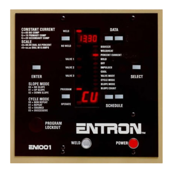
Page 154: Appendix Een1000/En1001 Bench Controls
E-2.0 CONTROL PANEL LAYOUT Figure E-1. Control Panel layout Additions to Control Panel of EN1000-B and EN1001-B Controls include Polarity Reverse switch (Item 32) and programming information for HALF CYCLE operation. Page 154 • 700120S • ENTRON Controls, LLC. - Page 155 Table E-1. VALVE codes CODE TS1-SV1 NOTICE S.S. S.S. S.S.=01 01 01 01 01) can be programmed but is not available in the S.S. EXTERNAL SCHEDULE SELECT (S.S. EN1000-B and EN1001-B Controls. ENTRON Controls, LLC. • 700120S • Page 155...
- Page 156 APPENDIX E EN1000/EN1001 BENCH CONTROLS (cont.) E-3.0 INSTALLATION & MOUNTING DIAGRAMS – “B” CABINET Figure E-2. “B” Cabinet installation and mounting diagrams Page 156 • 700120S • ENTRON Controls, LLC.
- Page 157 APPENDIX E EN1000/EN1001 BENCH CONTROLS (cont.) E-4.0 TERMINAL STRIP DIAGRAM For Terminal Strip connections, see appropriate Wiring Diagram and Section 4.3.2 Terminal Strip Connections. Figure E-3. Terminal Strip TS1/PCB2 ENTRON Controls, LLC. • 700120S • Page 157...
-
Page 158: Appendix Fen1003 Three Phase Dc Controls
Views “B”, “C”, “D” and Note 2 on Wiring Diagrams. Transformer secondaries may be connected for half wave or full wave rectification. Figure F-1. TS10 connections Figure F-2. PCB3 SW1 and L1 Page 158 • 700120S • ENTRON Controls, LLC. - Page 159 Three fuses (F1, F2 and F3 – 1/4A) protect the control circuits in each phase. Fuses F6, F7, and F8 (2AG 1A) protect the valve circuits for each of the solenoid valve outputs. Figure F-5. EN1003 Front Panel ENTRON Controls, LLC. • 700120S • Page 159...
- Page 160 When the EN1003 Control is used in the inside delta wiring configuration, each SCR can fire an independent transformer regardless of the secondary configuration. Figure F-6. Inside delta configuration Figure F-7. Outside delta and “Y” configuration Page 160 • 700120S • ENTRON Controls, LLC.
-
Page 161: Appendix Gen1000 Series Response Times
All data in Table G-1 was tested on Sequence Control & Display Board 600572-002 with PROM firmware version 619016-002CC or 619016-992. Worst-case times were recorded. High Speed operation using Binary Select was not tested. ENTRON Controls, LLC. • 700120S • Page 161... -
Page 162: Appendix Himu Mounting Options
Figure H-1. IMU rotation option NOTICE The standard IMU configuration on the left does not require as much clearance space below the Dial Plate mounting as the new configuration on the right. Page 162 • 700120S • ENTRON Controls, LLC. - Page 163 When control is wired for 380 VAC Operation, add quantity one (1) TS1 label P/N 460105 for 230/460/575 VAC Operation. USED ON: EN1001-IMU (SCR) Wiring Diagram 421423 EN1001-IMU/485 (SCR) Wiring Diagram 421423-002 EN1001/VS-IMU (SCR) Wiring Diagram 421423-003 EN1000-IMU (SCR) Wiring Diagram 421424 ENTRON Controls, LLC. • 700120S • Page 163...
-
Page 164: Appendix Iprogramming Worksheets
APPENDIX I PROGRAMMING WORKSHEETS Page 164 • 700120S • ENTRON Controls, LLC. - Page 165 APPENDIX I PROGRAMMING WORKSHEETS (cont.) ENTRON Controls, LLC. • 700120S • Page 165...
- Page 166 APPENDIX I PROGRAMMING WORKSHEETS (cont.) Page 166 • 700120S • ENTRON Controls, LLC.
- Page 167 APPENDIX I PROGRAMMING WORKSHEETS (cont.) ENTRON Controls, LLC. • 700120S • Page 167...
Need help?
Do you have a question about the EN1000 series and is the answer not in the manual?
Questions and answers