Sign In
Upload
Manuals
Brands
Endress+Hauser Manuals
Measuring Instruments
Proline Promass F 500
Endress+Hauser Proline Promass F 500 Manuals
Manuals and User Guides for Endress+Hauser Proline Promass F 500. We have
6
Endress+Hauser Proline Promass F 500 manuals available for free PDF download: Operating Instructions Manual, Special Documentation, Brief Operating Instructions
Endress+Hauser Proline Promass F 500 Operating Instructions Manual (268 pages)
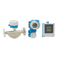
Coriolis Flowmeter HART
Brand:
Endress+Hauser
| Category:
Measuring Instruments
| Size: 10 MB
Table of Contents
Table of Contents
3
About this Document
6
Document Function
6
Symbols
6
Safety Symbols
6
Electrical Symbols
6
Communication-Specific Symbols
6
Tool Symbols
7
Symbols for Certain Types of Information
7
Symbols in Graphics
7
Documentation
8
Registered Trademarks
8
Safety Instructions
9
Requirements for the Personnel
9
Intended Use
9
Workplace Safety
10
Operational Safety
10
Product Safety
10
Security
11
Device-Specific IT Security
11
Protecting Access Via Hardware Write Protection
11
Protecting Access Via a Password
11
Infrastructure Mode
12
Access Via Web Server
12
Access Via OPC-UA
12
Access Via Service Interface (CDI-RJ45)
13
Product Description
14
Product Design
14
Proline 500 - Digital
14
Proline 500
14
Incoming Acceptance and Product
16
Identification
16
Incoming Acceptance
16
Product Identification
16
Incoming Acceptance and Product Identification
17
Transmitter Nameplate
17
Sensor Nameplate
19
Symbols on the Device
20
Storage and Transport
21
Storage Conditions
21
Transporting the Product
21
Measuring Devices Without Lifting Lugs
21
Measuring Devices with Lifting Lugs
22
Transporting with a Fork Lift
22
Packaging Disposal
22
Installation
22
Mounting Requirements
22
Installation Position
22
Inlet and Outlet Runs
24
Installation Dimensions
24
Environmental and Process Requirements
25
Ambient Temperature Range
25
Static Pressure
25
Thermal Insulation
25
Special Mounting Instructions
27
Weather Protection Cover
29
Installing the Measuring Instrument
30
Required Tools
30
Preparing the Measuring Instrument
30
Mounting the Measuring Device
30
Mounting the Transmitter Housing: Proline 500 - Digital
31
Wall Mounting
32
Drill the Holes
32
Mounting the Transmitter Housing: Proline 500
33
Turning the Transmitter Housing: Proline 500
34
Turning the Display Module: Proline 500
34
Post-Installation Check
35
Electrical Connection
36
Electrical Safety
36
Connecting Requirements
36
Required Tools
36
Requirements for Connection Cable
36
Terminal Assignment
41
Preparing the Measuring Device
41
Connecting the Measuring Instrument: Proline 500 - Digital
43
Connecting the Connecting Cable
43
Connecting the Signal Cable and the Supply Voltage Cable
48
Connecting the Measuring Instrument: Proline 500
50
Fitting the Connecting Cable
50
Connecting the Signal Cable and the Supply Voltage Cable
54
Potential Equalization
56
Requirements
56
Special Connection Instructions
57
Connection Examples
57
HART Input
58
Current Output 4-20 Ma
58
Pulse/Frequency Output
59
Switch Output
59
Relay Output
60
Current Input
60
Ensuring the Degree of Protection
61
Post-Connection Check
61
Operation Options
63
Overview of Operation Options
63
Structure and Function of the Operating Menu
64
Structure of the Operating Menu
64
Operating Philosophy
65
Access to Operating Menu Via Local Display
66
Operational Display
66
Status Signals
66
Display Area
67
Navigation View
69
Navigation Path
69
Locking Procedure
70
Editing View
71
Numeric Editor
71
Text Editor
71
Operating Elements
73
Opening the Context Menu
73
Navigating and Selecting from List
75
Calling the Parameter Directly
75
Calling up Help Text
76
Changing the Parameters
76
User Roles and Related Access Authorization
77
Disabling Write Protection Via Access Code
77
Enabling and Disabling the Keypad
78
Access to Operating Menu Via Web Browser
78
Function Range
78
Requirements
79
Connecting the Device
80
Logging on
82
User Interface
83
Function Row
83
Navigation Area
83
Disabling the Web Server
84
Logging out
84
Access to the Operating Menu Via the Operating Tool
85
Connecting the Operating Tool
85
Service Interface
86
Enter the Password
88
Field Xpert SFX350, SFX370
89
Fieldcare
89
Devicecare
90
AMS Device Manager
90
Field Communicator 475
91
Simatic Pdm
91
System Integration
92
Overview of Device Description Files
92
Current Version Data for the Device
92
Operating Tools
92
Measured Variables Via HART Protocol
93
Device Variables
96
Other Settings
97
Parameter Overview with Brief Description
97
Commissioning
100
Post-Mounting and Post-Connection Check
100
Switching on the Measuring Device
100
Setting the Operating Language
100
Configuring the Measuring Instrument
100
Defining the Tag Name
102
Setting the System Units
102
Selecting and Setting the Medium
105
Endress+Hauser
105
Displaying the I/O Configuration
107
Configuring the Current Input
108
Configuring the Status Input
109
Configuring the Current Output
110
Configuring the Pulse/Frequency
115
Switch Output
115
Configuring the Relay Output
124
10.4.10 Configuring the Double Pulse Output
127
10.4.11 Configuring the Local Display
128
Endress+Hauser
129
10.4.12 Configuring the Low Flow Cut off
133
10.4.13 Configuring Partially Filled Pipe Detection
134
Advanced Settings
135
Using the Parameter to Enter the Access Code
136
Calculated Process Variables
136
Carrying out a Sensor Adjustment
137
Density Adjustment
138
Configuring the Totalizer
143
Carrying out Additional Display Configurations
146
Endress+Hauser
147
WLAN Configuration
152
Configuration Management
154
Function Scope of the "Configuration Management" Parameter
155
Using Parameters for Device Administration
155
Simulation
156
Protecting Settings from Unauthorized Access
160
Write Protection Via Access Code
160
Write Protection Via Write Protection Switch
161
Operation
164
Reading off the Device Locking Status
164
Adjusting the Operating Language
164
Configuring the Display
164
Reading off Measured Values
164
Measured Variables" Submenu
165
Totalizer" Submenu
175
Input Values" Submenu
176
Output Values
177
Adapting the Measuring Device to the Process Conditions
179
Performing a Totalizer Reset
179
Parameter Overview with Brief Description
180
Function Scope of "Control Totalizer" Parameter
181
Function Range of "Reset All Totalizers" Parameter
181
Displaying the Measured Value History
181
Gas Fraction Handler
185
Measurement Mode" Submenu
185
Medium Index" Submenu
186
Diagnostics and Troubleshooting
187
General Troubleshooting
187
Diagnostic Information Via Light Emitting Diodes
190
Transmitter
190
Sensor Connection Housing
192
Diagnostic Information on Local Display
193
Diagnostic Message
193
Diagnostic Information
194
Calling up Remedial Measures
195
Diagnostic Information in the Web Browser
196
Diagnostic Options
196
Calling up Remedy Information
197
Diagnostic Information in Fieldcare or
198
Diagnostic Options
198
Calling up Remedy Information
199
Adapting the Diagnostic Information
200
Adapting the Diagnostic Behavior
200
Adapting the Status Signal
200
Overview of Diagnostic Information
202
Pending Diagnostic Events
207
Diagnostics List
207
12.10 Event Logbook
209
12.10.1 Reading out the Event Logbook
209
12.10.2 Filtering the Event Logbook
209
12.10.3 Overview of Information Events
210
12.11 Resetting the Measuring Device
212
12.11.1 Function Range of "Device Reset" Parameter
212
12.12 Device Information
213
12.13 Firmware History
215
12.14 Device History and Compatibility
216
Maintenance
217
Maintenance Work
217
Exterior Cleaning
217
Internal Cleaning
217
Measuring and Test Equipment
217
Endress+Hauser Services
217
Repair
218
General Notes
218
Repair and Conversion Concept
218
Notes for Repair and Conversion
218
Spare Parts
218
Endress+Hauser Services
218
Return
218
Disposal
219
Removing the Measuring Device
219
Disposing of the Measuring Device
219
Accessories
220
Device-Specific Accessories
220
For the Transmitter
220
For the Sensor
221
Communication-Specific Accessories
221
Service-Specific Accessories
222
System Components
223
Technical Data
224
Application
224
Function and System Design
224
Input
225
Direct Measured Variables
225
Status Input
226
Output
227
Output Signal
227
Current Output 4 to 20 Ma
228
Local Display
232
Web Browser
233
Light Emitting Diodes (LED)
233
Power Supply
233
Performance Characteristics
235
Flow Values
236
Accuracy of Outputs
237
Mounting
240
Environment
240
Process
242
Pressure-Temperature Ratings
242
Flow Limit
244
16.10 Custody Transfer
245
16.11 Mechanical Construction
245
Transmitter Housing
246
Connecting Cables
247
High-Temperature Version
248
16.12 User Interface
250
Historom Data Management
252
16.13 Certificates and Approvals
253
Application Packages
256
Heartbeat Verification
257
Heartbeat Monitoring
257
16.15 Accessories
258
Supplemental Documentation
259
Technical Information
259
Description of Device Parameters
259
Special Documentation
260
Installation Instructions
260
Index
261
Advertisement
Endress+Hauser Proline Promass F 500 Operating Instructions Manual (210 pages)
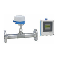
Thermal mass flowmeter HART
Brand:
Endress+Hauser
| Category:
Measuring Instruments
| Size: 7 MB
Table of Contents
Table of Contents
3
About this Document
6
Document Function
6
Symbols
6
Safety Symbols
6
Electrical Symbols
6
Communication-Specific Symbols
6
Tool Symbols
7
Symbols for Certain Types of Information
7
Symbols in Graphics
7
Documentation
8
Document Function
8
Registered Trademarks
8
Safety Instructions
9
Requirements for the Personnel
9
Intended Use
9
Workplace Safety
10
Operational Safety
10
Product Safety
10
Security
11
Device-Specific IT Security
11
Protecting Access Via Hardware Write Protection
11
Protecting Access Via a Password
11
Access Via Web Server
12
Access Via Service Interface (CDI-RJ45)
13
Product Description
14
Product Design
14
Proline 500 - Digital
14
Proline 500
14
Incoming Acceptance and Product
15
Identification
15
Incoming Acceptance
15
Product Identification
15
Transmitter Nameplate
16
Sensor Nameplate
17
Symbols on the Device
18
Storage and Transport
18
Storage Conditions
18
Transporting the Product
18
Packaging Disposal
19
Mounting
20
Mounting Requirements
20
Installation Position
20
Environment and Process Requirements
25
Special Mounting Instructions
27
Mounting the Measuring Device
27
Required Tool
27
Preparing the Measuring Device
27
Mounting the Measuring Device
28
Mounting the Transmitter Housing: Proline 500 - Digital
28
Post-Installation Check
30
Electrical Connection
31
Electrical Safety
31
Connection Requirements
31
Required Tools
31
Requirements for Connection Cable
31
Terminal Assignment
34
Preparing the Measuring Device
35
Connecting the Measuring Device: Proline 500 - Digital
36
Connecting the Connecting Cable
36
Connecting the Signal Cable and the Supply Voltage Cable
39
Potential Equalization
40
Requirements
40
Special Connection Instructions
41
Connection Examples
41
Ensuring the Degree of Protection
44
Degree of Protection IP68, Type 6P Enclosure, with "Cust-Potted" Option
45
Post-Connection Check
45
Operation Options
46
Overview of Operation Options
46
Structure and Function of the Operating Menu
47
Structure of the Operating Menu
47
Operating Philosophy
48
Access to Operating Menu Via Local Display
49
Operational Display
49
Navigation View
51
Editing View
53
Operating Elements
55
Opening the Context Menu
55
Navigating and Selecting from List
57
Calling the Parameter Directly
57
Calling up Help Text
58
Changing the Parameters
58
User Roles and Related Access Authorization
59
Disabling Write Protection Via Access
59
Code
59
Enabling and Disabling the Keypad Lock
60
Access to Operating Menu Via Web Browser
60
Function Range
60
Requirements
61
Establishing a Connection
62
Logging on
64
User Interface
65
Disabling the Web Server
66
Logging out
66
Access to the Operating Menu Via the Operating Tool
67
Connecting the Operating Tool
67
Field Xpert SFX350, SFX370
70
Fieldcare
70
Devicecare
71
AMS Device Manager
72
Field Communicator 475
72
Simatic Pdm
72
System Integration
73
Overview of Device Description Files
73
Current Version Data for the Device
73
Operating Tools
73
Measured Variables Via HART Protocol
73
Device Variables
74
Other Settings
75
Commissioning
78
Post-Mounting and Post-Connection Check
78
Switching on the Measuring Device
78
Setting the Operating Language
78
Configuring the Measuring Device
79
Defining the Tag Name
80
Configuring the Measurement Mode
80
Configuring Reference Conditions
84
Sensor Adjustment
85
Setting the System Units
86
Displaying the I/O Configuration
88
Configuring the Current Input
89
Configuring the Status Input
90
Configuring the Current Output
91
Configuring the Pulse/Frequency
94
Switch Output
94
Configuring the Relay Output
100
Configuring the Local Display
101
Configuring the Low Flow Cut off
104
Advanced Settings
105
Using the Parameter to Enter the Access Code
105
Configuring the Totalizer
105
Carrying out Additional Display Configurations
107
WLAN Configuration
110
Configuration Management
111
Using Parameters for Device Administration
113
In-Situ Adjustment
114
Configuration Management
121
Function Scope of the "Configuration Management" Parameter
121
Simulation
122
Protecting Settings from Unauthorized Access
124
Write Protection Via Access Code
124
Write Protection Via Write Protection Switch
126
Operation
128
Reading off the Device Locking Status
128
Adjusting the Operating Language
128
Configuring the Display
128
Reading off Measured Values
128
Process Variables
129
System Values
130
Totalizer" Submenu
130
Input Values" Submenu
131
Output Values
132
Adapting the Measuring Device to the Process
134
Conditions
134
Performing a Totalizer Reset
134
Function Scope of "Control Totalizer" Parameter
135
Function Range of "Reset All Totalizers" Parameter
135
Displaying Data Logging
135
Diagnostics and Troubleshooting
138
General Troubleshooting
138
Diodes
141
Transmitter
141
Sensor Connection Housing
142
Diagnostic Information on Local Display
143
Diagnostic Message
143
Calling up Remedial Measures
145
Diagnostic Information in the Web Browser
146
Diagnostic Options
146
Calling up Remedy Information
147
Diagnostic Options
148
Calling up Remedy Information
149
Adapting the Diagnostic Information
150
Adapting the Diagnostic Behavior
150
Adapting the Status Signal
150
Overview of Diagnostic Information
152
Pending Diagnostic Events
156
Diagnostic List
156
11.10 Event Logbook
158
11.10.1 Reading out the Event Logbook
158
11.10.2 Filtering the Event Logbook
158
11.10.3 Overview of Information Events
159
11.11 Resetting the Measuring Device
161
11.11.1 Function Range of "Device Reset" Parameter
161
11.12 Device Information
162
11.13 Firmware History
164
Maintenance
165
Maintenance Tasks
165
Exterior Cleaning
165
Sensing Element Cleaning
165
Recalibration
166
Measuring and Test Equipment
166
Endress+Hauser Services
166
Repair
167
General Information
167
Repair and Conversion Concept
167
Notes for Repair and Conversion
167
Spare Parts
167
Endress+Hauser Services
167
Return
167
Disposal
168
Removing the Measuring Device
168
Disposing of the Measuring Device
168
Accessories
169
Device-Specific Accessories
169
For the Transmitter
169
Communication-Specific Accessories
170
Service-Specific Accessories
171
System Components
171
Technical Data
172
Application
172
Function and System Design
172
Input
173
Output
178
Power Supply
183
Performance Characteristics
185
Mounting
186
Environment
186
Process
189
15.10 Mechanical Construction
190
15.11 Display and User Interface
193
15.12 Certificates and Approvals
197
15.13 Application Packages
201
15.14 Accessories
202
15.15 Documentation
202
Index
204
Endress+Hauser Proline Promass F 500 Operating Instructions Manual (218 pages)
Coriolis flowmeter Modbus RS485
Brand:
Endress+Hauser
| Category:
Measuring Instruments
| Size: 9 MB
Table of Contents
Operating Instructions
1
Table of Contents
3
1 Document Information
6
Tool Symbols
7
Documentation
8
Registered Trademarks
9
2 Basic Safety Instructions
10
Workplace Safety
11
IT Security
12
Access Via Fieldbus
13
3 Product Description
14
Proline 500
15
4 Incoming Acceptance and Product
16
Identification
16
Product Identification
17
Sensor Nameplate
19
Symbols on Measuring Device
20
5 Storage and Transport
21
Measuring Devices with Lifting Lugs
22
Process
25
Special Mounting Instructions
28
Mounting the Measuring Device
31
Proline 500 – Digital
32
Proline 500
33
Proline 500
34
6.2.7 Turning the Display Module: Proline
35
Post-Installation Check
36
7 Electrical Connection
37
Terminal Assignment
40
Preparing the Measuring Device
41
Digital
42
Supply Voltage Cable
47
Connecting the Connecting Cable
49
Supply Voltage Cable
53
Ensure Potential Equalization
55
Hardware Settings
59
Enabling the Terminating Resistor
60
Ensuring the Degree of Protection
61
Post-Connection Check
62
8 Operation Options
63
Menu
64
Operating Philosophy
65
Operational Display
66
Operating Elements
71
Opening the Context Menu
72
Navigating and Selecting from List
74
Calling up Help Text
75
8.3.9 Changing the Parameters
76
Authorization
77
Browser
78
Establishing a Connection
80
Logging on
81
User Interface
82
Disabling the Web Server
83
Connecting the Operating Tool
84
9 System Integration
89
Modbus RS485 Information
90
Register Information
91
10 Commissioning
93
Defining the Tag Name
94
10.3.2 Setting the System Units
95
Interface
96
Configuring the Current Input
100
Configuring the Status Input
101
Configuring the Current Output
102
Switch Output
105
Configuring the Relay Output
114
Configuring the Local Display
117
Configuring the Low Flow Cut off
120
10.3.14 Configuring the Partial Filled Pipe
121
Advanced Settings
122
Calculated Values
123
Carrying out a Sensor Adjustment
124
Configuring the Totalizer
125
Configurations
127
WLAN Configuration
130
Configuration Management
131
Using Parameters for Device Administration
133
Simulation
134
15 Access
137
Switch
139
Operation
141
Conditions
148
Function Scope of the "Control Totalizer" Parameter
149
12 Diagnostics and Troubleshooting
152
Transmitter
154
Diagnostic Message
158
Calling up Remedial Measures
160
Fieldcare
161
Adapting the Diagnostic Information
163
Overview of Diagnostic Information
164
Pending Diagnostic Events
168
Diagnostic List
169
Filtering the Event Logbook
170
Resetting the Measuring Device
172
Firmware History
174
13 Maintenance
175
14 Repairs
176
Disposal
177
Accessories
178
For the Sensor
179
16 Technical Data
181
Input
182
Output
185
Power Supply
189
Performance Characteristics
190
Installation
195
Process
196
Mechanical Construction
198
Operability
202
Advertisement
Endress+Hauser Proline Promass F 500 Special Documentation (52 pages)
Brand:
Endress+Hauser
| Category:
Transmitter
| Size: 1 MB
Table of Contents
Table of Contents
3
Manufacturer's Declaration
4
Safety-Related Characteristic Values
5
Certificate
7
About this Document
7
Document Function
7
Using this Document
7
Symbols
7
Supplementary Device Documentation
9
Design
10
Permitted Device Types
10
Marking
12
Notes on the Redundant Use of Multiple
13
Sensors
13
Basic Conditions for Use in Safety-Related Applications
15
Safety Measured Error
16
Useful Lifetime of Electrical
18
Components
18
Commissioning
18
And Configuration)
18
Requirements for the Personnel
18
Installation
18
Operation
19
Parameter Configuration for Safety
19
Related Applications
19
Operation
29
Device Behavior During Power-Up
29
Device Behavior in Safety Function
29
Demand Mode
29
Safe States
30
Device Behavior in Event of Alarms and Warnings
30
Alarm and Warning Messages
30
Proof Testing
31
Test Sequence a (PTC = 99 %)
32
Test Sequence C (PTC = 98 %)
35
Test Sequence D (PTC = 36 %)
37
Test Sequence E (PTC = 19 %)
40
Test Sequence F (PTC = 0 %)
42
Verification Criterion
43
Repair and Error Handling
43
Maintenance
43
Repair
44
Modification
44
Taking out of Service
45
Disposal
45
Appendix
45
Structure of the Measuring System
45
Commissioning or Proof Test Report
48
Verification or Calibration
50
Version History
50
Endress+Hauser Proline Promass F 500 Brief Operating Instructions (44 pages)
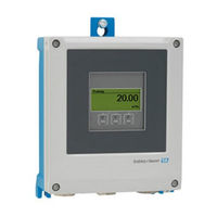
Transmitter with Coriolis sensor
Brand:
Endress+Hauser
| Category:
Transmitter
| Size: 2 MB
Table of Contents
Table of Contents
4
Document Information
5
Symbols Used
5
Basic Safety Instructions
7
Requirements for the Personnel
7
Designated Use
7
Workplace Safety
8
Operational Safety
8
Product Safety
9
Security
9
Device-Specific IT Security
9
Product Description
10
Installation
11
Post Mounting
11
Wall Mounting
12
Transmitter Post-Installation Check
12
Electrical Connection
13
Connection Conditions
13
Connecting the Measuring Device
19
Hardware Settings
31
Ensuring Potential Equalization
33
Ensuring the Degree of Protection
33
Post-Connection Check
34
Operation Options
35
Overview of Operation Options
35
Structure and Function of the Operating Menu
36
Access to the Operating Menu Via the Local Display
37
Access to the Operating Menu Via the Operating Tool
40
Access to the Operating Menu Via the Web Server
40
System Integration
40
Commissioning
40
Function Check
40
Setting the Operating Language
41
Configuring the Measuring Device
41
Protecting Settings from Unauthorized Access
42
Diagnostic Information
42
Endress+Hauser Proline Promass F 500 Brief Operating Instructions (36 pages)
Transmitter with thermal mass flowmeter sensor
Brand:
Endress+Hauser
| Category:
Transmitter
| Size: 1 MB
Table of Contents
Table of Contents
4
About this Document
5
Symbols Used
5
Safety Instructions
7
Requirements for the Personnel
7
Designated Use
7
Workplace Safety
8
Operational Safety
8
Product Safety
9
Security
9
Device-Specific IT Security
9
Product Description
10
Installation
11
Post Mounting
11
Wall Mounting
12
Transmitter Post-Installation Check
12
Electrical Connection
13
Electrical Safety
13
Connection Conditions
13
Connecting the Measuring Device
20
Ensuring Potential Equalization
25
Ensuring the Degree of Protection
25
Post-Connection Check
26
Operation Options
27
Overview of Operation Options
27
Structure and Function of the Operating Menu
28
Access to the Operating Menu Via the Local Display
29
Access to the Operating Menu Via the Operating Tool
32
Access to the Operating Menu Via the Web Server
32
System Integration
32
Commissioning
32
Function Check
32
Setting the Operating Language
33
Configuring the Measuring Device
33
Protecting Settings from Unauthorized Access
34
Diagnostic Information
34
Advertisement
Related Products
Endress+Hauser prolevel FMC 661
Endress+Hauser Levelflex FMP54
Endress+Hauser prosonic flow 92
Endress+Hauser Waterpilot FMX21
Endress+Hauser Proline Prowirl F 200
Endress+Hauser Waterpilot FMX167
Endress+Hauser Liquiphant S FTL71-**********N Series
Endress+Hauser Nivocompact FTC 131
Endress+Hauser Nivocompact FTC 231
Endress+Hauser Proline Promass F 300
Endress+Hauser Categories
Measuring Instruments
Transmitter
Radar
Switch
Accessories
More Endress+Hauser Manuals
Login
Sign In
OR
Sign in with Facebook
Sign in with Google
Upload manual
Upload from disk
Upload from URL