Sign In
Upload
Manuals
Brands
Endress+Hauser Manuals
Measuring Instruments
Proline Promass E 300
Endress+Hauser Proline Promass E 300 Manuals
Manuals and User Guides for Endress+Hauser Proline Promass E 300. We have
2
Endress+Hauser Proline Promass E 300 manuals available for free PDF download: Operating Instructions Manual
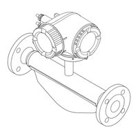
Endress+Hauser Proline Promass E 300 Operating Instructions Manual (244 pages)
Coriolis Flowmeter EtherNet/IP
Brand:
Endress+Hauser
| Category:
Measuring Instruments
| Size: 8 MB
Table of Contents
Table of Contents
3
About this Document
6
Document Function
6
Symbols
6
Safety Symbols
6
Electrical Symbols
6
Communication-Specific Symbols
6
Symbols for Certain Types of Information
7
Tool Symbols
7
Symbols in Graphics
7
Documentation
8
Registered Trademarks
8
Safety Instructions
9
Requirements for the Personnel
9
Intended Use
9
Workplace Safety
10
Operational Safety
10
Product Safety
10
Security
11
Device-Specific IT Security
11
Protecting Access Via Hardware Write Protection
11
Protecting Access Via a Password
11
Infrastructure Mode
12
Access Via Web Server
12
Access Via Service Interface (CDI-RJ45)
12
Product Description
14
Product Design
14
Incoming Acceptance and Product
15
Identification
15
Incoming Acceptance
15
Product Identification
15
Transmitter Nameplate
16
Sensor Nameplate
17
Symbols on the Device
18
Storage and Transport
19
Storage Conditions
19
Transporting the Product
19
Measuring Devices Without Lifting Lugs
19
Measuring Devices with Lifting Lugs
20
Transporting with a Fork Lift
20
Packaging Disposal
20
Mounting
21
Mounting Requirements
21
Installation Position
21
Inlet and Outlet Runs
23
Environmental and Process Requirements
23
Ambient Temperature Range
23
Static Pressure
23
Special Installation Instructions
25
Weather Protection Cover
26
Mounting the Measuring Instrument
27
Required Tools
27
Preparing the Measuring Instrument
27
Mounting the Measuring Device
27
Turning the Transmitter Housing
28
Turning the Display Module
29
Post-Installation Check
30
Electrical Connection
31
Electrical Safety
31
Connecting Requirements
31
Required Tools
31
Requirements for Connection Cable
31
Endress+Hauser
33
Terminal Assignment
34
Available Device Plugs
34
Pin Assignment of Device Plug
34
Preparing the Measuring Device
34
Connecting the Measuring Instrument
35
Connecting the Transmitter
35
Connecting Connector
35
Integrating the Transmitter into a Network
38
Connecting the Remote Display and Operating Module DKX001
40
Potential Equalization
40
Requirements
40
Special Connection Instructions
41
Connection Examples
41
Current Output 4-20 Ma
41
Pulse/Frequency Output
42
Switch Output
42
Relay Output
43
Current Input
43
Status Input
43
Hardware Settings
44
Setting the Device Address
44
Activating the Default IP Address
45
Ensuring the Degree of Protection
45
Post-Connection Check
46
Operation Options
47
Overview of Operation Options
47
Structure and Function of the Operating Menu
48
Structure of the Operating Menu
48
Operating Philosophy
49
Access to Operating Menu Via Local Display
50
Operational Display
50
Status Signals
50
Display Area
51
Navigation View
53
Navigation Path
53
Locking Procedure
54
Editing View
55
Numeric Editor
55
Text Editor
55
Operating Elements
57
Opening the Context Menu
57
Navigating and Selecting from List
59
Calling the Parameter Directly
59
Calling up Help Text
60
Changing the Parameters
60
User Roles and Related Access Authorization
61
Disabling Write Protection Via Access Code
61
Enabling and Disabling the Keypad
62
Access to Operating Menu Via Web Browser
62
Function Range
62
Requirements
63
Connecting the Device
64
Enter the Password
66
Logging on
67
User Interface
67
Function Row
67
Disabling the Web Server
68
Logging out
69
Access to the Operating Menu Via the Operating Tool
69
Connecting the Operating Tool
69
Star Topology
70
Ring Topology
70
Service Interface
71
Fieldcare
73
Devicecare
74
System Integration
75
Overview of Device Description Files
75
Current Version Data for the Device
75
Operating Tools
75
Overview of System Files
75
Integrating the Measuring Device in the
76
Cyclic Data Transmission
76
Block Model
76
Input and Output Groups
77
Possible Configurations
77
Possible Connections
78
Diagnostic Information Via Ethernet/Ip
87
Commissioning
92
Post-Mounting and Post-Connection Check
92
Switching on the Measuring Device
92
Connecting Via Fieldcare
92
Setting the Operating Language
92
Configuring the Measuring Instrument
93
Defining the Tag Name
94
Setting the System Units
94
Parameter Overview with Brief Description
95
Configuring the Communication Interface
96
Selecting and Setting the Medium
98
Displaying the I/O Configuration
99
Configuring the Current Input
100
Configuring the Status Input
101
Configuring the Current Output
102
Configuring the Pulse/Frequency/Switch Output
105
10.5.10 Configuring the Relay Output
113
10.5.11 Configuring the Local Display
116
10.5.12 Configuring the Low Flow Cut off
120
10.5.13 Configuring Partially Filled Pipe Detection
121
Advanced Settings
122
Using the Parameter to Enter the Access Code
123
Calculated Process Variables
123
Carrying out a Sensor Adjustment
125
Density Adjustment
125
Configuring the Totalizer
131
Carrying out Additional Display Configurations
133
Endress+Hauser
133
WLAN Configuration
137
Configuration Management
139
Function Scope of the "Configuration Management" Parameter
140
Using Parameters for Device Administration
140
Simulation
142
Protecting Settings from Unauthorized Access
145
Write Protection Via Access Code
145
Write Protection Via Write Protection Switch
147
Operation
149
Reading off the Device Locking Status
149
Adjusting the Operating Language
149
Configuring the Display
149
Reading off Measured Values
149
Measured Variables" Submenu
150
Density
152
Temperature
152
Concentration
152
Target Corrected Volume Flow
153
Carrier Corrected Volume Flow
153
Ctl
154
Cpl
154
Ctpl
154
Totalizer" Submenu
160
Input Values" Submenu
160
Output Values
162
Adapting the Measuring Device to the Process Conditions
164
Performing a Totalizer Reset
164
Function Scope of "Control Totalizer" Parameter
165
Function Range of "Reset All Totalizers" Parameter
166
Displaying the Measured Value History
166
Diagnostics and Troubleshooting
170
General Troubleshooting
170
Diagnostic Information Via Light Emitting Diodes
172
Transmitter
172
Diagnostic Information on Local Display
174
Diagnostic Message
174
Diagnostic Information
175
Calling up Remedial Measures
176
Diagnostic Information in the Web Browser
176
Diagnostic Options
176
Calling up Remedy Information
177
Diagnostic Information in Fieldcare or
177
Diagnostic Options
177
Diagnostic Information Via Communication Interface
179
Reading out Diagnostic Information
179
Adapting the Diagnostic Information
179
Adapting the Diagnostic Behavior
179
Overview of Diagnostic Information
179
Diagnostic of Sensor
180
Diagnostic of Electronic
181
Diagnostic of Configuration
185
Diagnostic of Process
189
Pending Diagnostic Events
193
12.10 Diagnostics List
193
12.11 Event Logbook
194
12.11.1 Reading out the Event Logbook
194
Information Events
194
12.11.2 Filtering the Event Logbook
195
12.11.3 Overview of Information Events
195
12.12 Resetting the Measuring Device
196
12.12.1 Function Range of "Device Reset" Parameter
196
12.13 Device Information
197
12.14 Firmware History
198
Maintenance
199
Maintenance Work
199
Exterior Cleaning
199
Internal Cleaning
199
Measuring and Test Equipment
199
Endress+Hauser Services
199
Repair
200
General Notes
200
Repair and Conversion Concept
200
Notes for Repair and Conversion
200
Spare Parts
200
Endress+Hauser Services
200
Return
200
Disposal
201
Removing the Measuring Device
201
Disposing of the Measuring Device
201
Accessories
202
Device-Specific Accessories
202
For the Transmitter
202
For the Sensor
203
Communication-Specific Accessories
203
Service-Specific Accessories
204
System Components
204
Technical Data
205
Application
205
Function and System Design
205
Input
206
Direct Measured Variables
206
Output
209
Output Signal
209
Light Emitting Diodes (LED)
214
Power Supply
215
Performance Characteristics
216
Zero Point Stability
217
Flow Values
217
Accuracy of Outputs
217
Mounting
220
Environment
220
Process
221
Flow Limit
222
16.10 Mechanical Construction
223
Transmitter Housing
224
Process Connections
225
16.11 Operability
226
Historom Data Management
229
16.12 Certificates and Approvals
230
16.13 Application Packages
232
Heartbeat Verification
233
Heartbeat Monitoring
233
16.14 Accessories
234
16.15 Supplementary Documentation
234
Technical Information
234
Installation Instructions
236
Index
237
Advertisement
Endress+Hauser Proline Promass E 300 Operating Instructions Manual (264 pages)
Coriolis flowmeter PROFINET
Brand:
Endress+Hauser
| Category:
Measuring Instruments
| Size: 10 MB
Table of Contents
Table of Contents
3
About this Document
6
Document Function
6
Symbols
6
Safety Symbols
6
Electrical Symbols
6
Communication Symbols
6
Tool Symbols
7
Symbols for Certain Types of Information
7
Symbols in Graphics
7
Documentation
8
Standard Documentation
8
Supplementary Device-Dependent Documentation
8
Registered Trademarks
8
Safety Instructions
10
Requirements for the Personnel
10
Designated Use
10
Workplace Safety
11
Operational Safety
11
Product Safety
12
Security
12
Device-Specific IT Security
12
Protecting Access Via Hardware Write Protection
12
Protecting Access Via a Password
13
Access Via Web Server
13
Access Via Service Interface (CDI-RJ45)
14
Product Description
15
Product Design
15
Incoming Acceptance and Product
16
Identification
16
Incoming Acceptance
16
Product Identification
16
Transmitter Nameplate
17
Sensor Nameplate
18
Symbols on Measuring Device
19
Storage and Transport
20
Storage Conditions
20
Transporting the Product
20
Measuring Devices Without Lifting Lugs
20
Measuring Devices with Lifting Lugs
21
Transporting with a Fork Lift
21
Packaging Disposal
21
Installation
22
Installation Conditions
22
Mounting Position
22
Environmental and Process Requirements
24
Special Mounting Instructions
26
Mounting the Measuring Device
27
Required Tools
27
Preparing the Measuring Device
28
Mounting the Measuring Device
28
Turning the Transmitter Housing
28
Turning the Display Module
29
Post-Installation Check
29
Electrical Connection
30
Connection Conditions
30
Required Tools
30
Requirements for Connecting Cable
30
Terminal Assignment
33
Device Plugs Available
33
Pin Assignment of Device Plug
33
Preparing the Measuring Device
33
Connecting the Measuring Device
34
Connecting the Transmitter
34
Integrating the Transmitter into a Network
38
Connecting the Remote Display and Operating Module DKX001
40
Ensuring Potential Equalization
40
Requirements
40
Special Connection Instructions
41
Connection Examples
41
Hardware Settings
44
Setting the Device Name
44
Activating the Default IP Address
46
Ensuring the Degree of Protection
46
Post-Connection Check
47
Operation Options
48
Overview of Operation Options
48
Structure and Function of the Operating Menu
49
Structure of the Operating Menu
49
Operating Philosophy
50
Display
51
Operational Display
51
Navigation View
52
Editing View
54
Operating Elements
56
Opening the Context Menu
56
Navigating and Selecting from List
58
Calling the Parameter Directly
58
Calling up Help Text
59
Changing the Parameters
59
User Roles and Related Access Authorization
60
Disabling Write Protection Via Access
60
Code
60
Enabling and Disabling the Keypad
61
Access to the Operating Menu Via the Web Browser
61
Function Range
61
Prerequisites
62
Establishing a Connection
63
Logging on
65
User Interface
66
Disabling the Web Server
67
Logging out
67
Access to the Operating Menu Via the Operating Tool
68
Connecting the Operating Tool
68
Fieldcare
71
Devicecare
72
System Integration
74
Overview of Device Description Files
74
Current Version Data for the Device
74
Operating Tools
74
Device Master File (GSD)
75
File Name of the Device Master File (GSD)
75
Cyclic Data Transmission
76
Overview of the Modules
76
Description of the Modules
76
Status Coding
84
Factory Setting
85
Startup Configuration
86
System Redundancy S2
87
Commissioning
88
Function Check
88
Switching on the Measuring Device
88
Connecting Via Fieldcare
88
Setting the Operating Language
88
Configuring the Measuring Device
89
Defining the Tag Name
90
Setting the System Units
90
Displaying the Communication
92
Interface
95
Displaying the I/O Configuration
95
Configuring the Current Input
96
Configuring the Status Input
97
Configuring the Current Output
98
Configuring the Pulse/Frequency
102
Switch Output
102
10.5.10 Configuring the Relay Output
111
10.5.11 Configuring the Local Display
114
10.5.12 Configuring the Low Flow Cut off
118
10.5.13 Configuring the Partial Filled Pipe
119
Advanced Settings
120
Using the Parameter to Enter the Access Code
121
Calculated Values
121
Carrying out a Sensor Adjustment
122
Configuring the Totalizer
123
Carrying out Additional Display Configurations
125
WLAN Configuration
129
Configuration Management
131
Using Parameters for Device Administration
133
Simulation
134
Protecting Settings from Unauthorized Access
137
Write Protection Via Access Code
138
Write Protection Via Write Protection
139
Switch
139
Operation
141
Reading the Device Locking Status
141
Adjusting the Operating Language
141
Configuring the Display
141
Reading Measured Values
141
Measured Variables" Submenu
142
Totalizer
143
Input Values" Submenu
144
Output Values
145
Adapting the Measuring Device to the Process
147
Conditions
147
Performing a Totalizer Reset
147
Function Scope of the "Control Totalizer" Parameter
148
Function Scope of the "Reset All Totalizers" Parameter
148
Showing Data Logging
148
Diagnostics and Troubleshooting
152
General Troubleshooting
152
Diagnostic Information Via Light Emitting
154
Diodes
154
Transmitter
154
Diagnostic Information on Local Display
156
Diagnostic Message
156
Calling up Remedial Measures
158
Diagnostic Information in the Web Browser
158
12.4.1 Diagnostic Options
158
Calling up Remedy Information
159
12.5 Diagnostic Information in Fieldcare or
159
Diagnostic Options
159
Adapting the Diagnostic Information
161
Adapting the Diagnostic Behavior
161
Overview of Diagnostic Information
164
Diagnostic of Sensor
164
Diagnostic of Electronic
171
Diagnostic of Configuration
188
Diagnostic of Process
201
Pending Diagnostic Events
215
Diagnostic List
215
12.10 Event Logbook
216
12.10.1 Reading out the Event Logbook
216
12.10.2 Filtering the Event Logbook
217
12.10.3 Overview of Information Events
217
12.11 Resetting the Measuring Device
218
12.11.1 Function Scope of the "Device Reset" Parameter
218
12.12 Device Information
219
12.13 Firmware History
221
Maintenance
222
Maintenance Tasks
222
Exterior Cleaning
222
Interior Cleaning
222
Measuring and Test Equipment
222
Endress+Hauser Services
222
Repair
223
General Notes
223
Repair and Conversion Concept
223
Notes for Repair and Conversion
223
Spare Parts
223
Endress+Hauser Services
223
Return
223
Disposal
224
Removing the Measuring Device
224
Disposing of the Measuring Device
224
Accessories
225
Device-Specific Accessories
225
For the Transmitter
225
For the Sensor
226
Communication-Specific Accessories
226
Service-Specific Accessories
227
System Components
227
Technical Data
228
Application
228
Function and System Design
228
Input
229
Output
232
Power Supply
237
Performance Characteristics
238
Installation
242
Environment
242
Process
243
16.10 Mechanical Construction
245
16.11 Human Interface
248
16.12 Certificates and Approvals
252
16.13 Application Packages
255
16.14 Accessories
256
16.15 Supplementary Documentation
256
Index
259
Advertisement
Related Products
Endress+Hauser Proline Promass E 300 HART
Endress+Hauser Proline Promass E 200
Endress+Hauser Proline Promass E 100
Endress+Hauser Analytik Jena multi EA 5000
Endress+Hauser Analytik Jena multi EA 5100
Endress+Hauser Liquiline To Go Ex CYM291
Endress+Hauser Endress+Hauser
Endress+Hauser Proline Promass E 500 PROFINET
Endress+Hauser Proline Prosonic Flow E 100 HART
Endress+Hauser Proline Promass E TB2 HART
Endress+Hauser Categories
Measuring Instruments
Transmitter
Radar
Switch
Accessories
More Endress+Hauser Manuals
Login
Sign In
OR
Sign in with Facebook
Sign in with Google
Upload manual
Upload from disk
Upload from URL